
Optical receivers with amplifiers are used to amplify the weak electrical signal generated by the photodetector. An illustration of the effective gainis given below. Note the presence of a gain peak around 1530nm and a semi-flat gain. Our optical receivers and detectors make photodetection easy and provide the lowest noise and cleanest response possible. Figure 1: Block diagram of an optical transmitter and receiver.
The optical receiver adds two types of noise namely thermal noise and shot noise. This application note provides an in-depth analysis of the complete receiver optical sensitivity and the potential power penalties related to the accumulation of random noise and inter-symbol interference (ISI) in both amplitude and timing. Ultimately, the noise influence on the signal will determine the system sensitivity. The challenge is to find a way to determine the. In the design of an optical receiver, it is vital that the module is capable of converting and shaping the optical signal while meeting or surpassing the maximum BER.
Q: How can receiver sensitivity be optimized? A: Receiver sensitivity can be optimized by employing techniques such as noise reduction, amplification, and signal processing, as well as careful detector selection and amplifier design. Optimizing SNR is all about tipping the balance in favor of the signal you want, so noise doesn't drown it out. That's the key to reliable communication and measurement. In essence, it measures how well a receiver can detect weak optical signals. amplitude shift keying (ASK) or on off keying (OOK). Voltage level is switched between two values, which are usually on and off.
The QSFP28 module provides 100GBase-LR4 throughput up to 10km over a standard pair of single-mode fiber (SMF) with duplex LC connectors. This transceiver is compliant with IEEE 802. 3ba 100GBASE-LR4, IEEE 802. 3bm, SFF-8665 and SFF-8636 standards. They are. The T1Nexus T1-QSFP-100G-SR-BDM is a parallel Quad Small Form-factor Pluggable (QSFP28) Bi-Direction optical module. The module integrates four host electrical data into two optical lanes (by Dual Wavelength VCSEL Bi-Directional Optical Interface, 850nm and 900nm) to allow optical communication. EdgeOptic's 100G-QSFP28-10 is a 100GBASE-LR4 QSFP28 transceiver: 10 km SMF, 4 LAN WDM wavelengths, 6. 125 Gbps) + OTU4 (112 Gbps) on the same wavelength plan. Codeable for Cisco, Juniper, Arista, Nokia, and 80+ other vendors. The module converts 4 input channels of 25Gb/s electrical data to 4 channels of LAN WDM optical signals and then multiplexes them into a single.
[PDF Version]
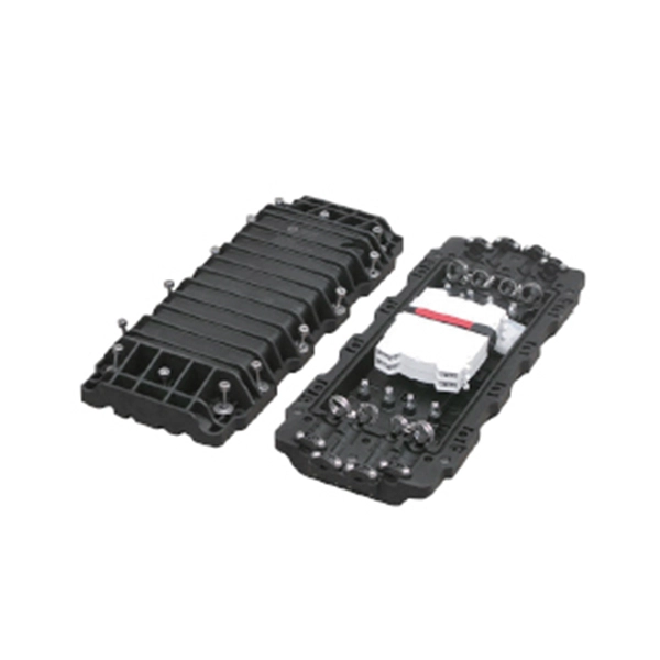
BS EN 60794-1-21 is maintained by GEL/86/1. The current release of this standard is: BS EN 60794-1-21:2015+A1:2020 Optical fibre cables. Basic optical cable test procedures. Mechanical tests methods This standard is available from the following sources:The International Electrotechnical Commission (IEC) is the leading global organization that prepares and publishes International Standards for all electrical, electronic and related technologies. The technical content of IEC publications is kept under constant review by the IEC. An objective of this document is to define general requirements and methodology. Listing of all FOA standards FOA Standard FOA-1: Testing Loss of Installed Fiber Optic Cable Plant, (Insertion Loss, TIA OFSTP-14, OFSTP-7, ISO/IEC 61280, ISO/IEC 14763, etc. IEC 60794-1-2:2021 applies to optical fibre cables for use with telecommunications equipment. Electrical properties are specified for optical ground wire (OPGW) and optical phase conductor (OPPC) cables.
[PDF Version]
QSFP-DD is a new module and cage/connector system similar to current QSFP, but with an additional row of contacts providing for an eight lane electrical interface. It is being developed by the QSFP-DD MSA as a key part of the industry's effort to enable high-speed solutions. The Cisco ® QSFP-DD Open Line System (QSFP-DD OLS) is a pluggable optical amplifier module that, together with the channel breakout options (described later), provides a simple yet powerful open. The QSFP-DD OLS is a pluggable open line system solution that can be directly hosted on a Cisco router. 8mm pitch and a dual-mating interface. QSFP-DD extends the use. Supporting the continuing growth in the bandwidth demand and datacenter traffic driven by networking and AI/ML requirements, the QSFP-DD (Double Density) Interconnect System delivers 8 lanes with up to 28 Gbps NRZ or 56 Gbps-PAM4 (up to 400 Gbps aggregate) in a compact footprint that is backward. Get best-in-class optics from legacy GBICs to cutting edge 1. Harness the power of Proline's quality by design. Explore our cutting-edge coding & testing lab.
[PDF Version]
Optical transceiver interoperability refers to the ability of transceiver modules from different manufacturers to function correctly with a range of networking equipment—switches, routers, servers, and optical transport gear—without compatibility issues. This guide dives deep into the core aspects of optical transceiver compatibility, common. When it comes to the connection between two fiber optic transceivers, the following four factors should be taken into considerations: wavelength, speed, fiber type, and the connection to switches. In a fiber link, the data is transmitted from one end to another, and fiber transceivers are. Several years ago, hyperscale network operators saw an opportunity for coherent Dense Wavelength Division Multiplexing (DWDM) transport optics to plug directly into routers for 400 Gbps Data Center Interconnections (DCIs) with reaches up to 120km. This point-to-point, IP-over-DWDM architecture. MSA (Multi-Source Agreement) standards define the mechanical, electrical, and management interfaces of optical transceivers, enabling multi-vendor interoperability, supply chain flexibility, and large-scale network deployment.
[PDF Version]
For such cables, we recommend using at least a 1. It's important to consider not only the rigidity of the jacket but also the breakout point of the assembly, where the strands exit the jacket and are encased in. 8 core single mode fiber optic cable should be selected by fiber mode, core count, cable structure, jacket material, installation route, tensile strength, attenuation test, reel length, and quantity. Selecting the right conduit ensures the cable's longevity, prevents signal degradation, and supports efficient installation and maintenance. They feature low attenuation benchmarks 2 and minimal dispersion. They use OS1 or OS2 OS1 or OS2 classifications to. Understanding the physics behind Single Mode vs Multi‑Mode Fiber is essential for selecting the right conduit for any optical network. Single‑mode fiber (SMF) employs an ultra‑narrow core—typically 8 to 10 µm in diameter—that permits only one propagation mode.
[PDF Version]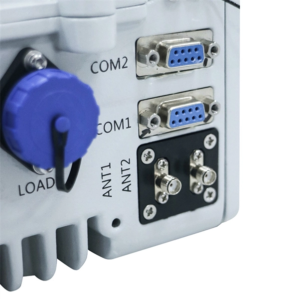
We know from our tutorials about Transformers that they can not only provide a step-down (or step-up) voltage, but they also provide electrical isolation between the higher voltage on the primary side and the lo.
Contact us for competitive quotes on any of our power communication and smart grid products
Get a Quote