
We describe NIST measurement services for the calibration of optical fiber power meters. To augment the absolute power measurements NIST provides nonlinearity, spectral responsivity, and uniformit.
A class of laboratory power meters has an extended sensitivity, of the order of -110 dBm. This is achieved by using a very small detector and lens combination, and also a mechanical light chopper at typically 270 Hz, so the meter actually measures AC light. This eliminates unavoidable dc electrical drift effects. If the light chopping is synchronized with an appropriate synchronous (or "lock-in") amplifier, further sensitivity gains are achieved. In practice, such instruments usually achieve lower absolute acc.
An optical power meter (OPM) is a device used to measure the power in an signal. The term usually refers to a device for testing average power in systems. Other general purpose light power measuring devices are usually called,, power meters (can be sensors or ), or lux meters. A typical optical power meter consists of a , measuring and display. The sens.
Work with optical power meter, provide light source steadily. Wavelengths : 1310/1550 (other wavelengths can be customized). Modulation Frequencies: 270Hz, 1 KHz, 2. The G10 Mini Optical Power Meter is a professional fiber optic testing device designed for accurate power level measurements in fiber optic networks. It has a wide range of power measurement and high accuracy, and can be used for absolute optical power measurement and. The AQ1200 Multi Field Tester OTDR is a compact and lightweight handheld OTDR optimized for the installation and maintenance of optical fiber cables. Designed with ease of use in mind to simplify field testing, improve work efficiency and ensure qualify results. Additionally it can record up to 100. 000 measurements and can transmit them via USB Micro-B port to a computer.
This guide compares five power meters from basic optical to full multi-generation PON and helps you match the right meter to your network. For most FTTH technicians, the XGS/GPON Power Meter ($484. 99) is the best all-around choice. If you're looking for the best optical power meters for fiber techs in 2025, I've tested top models that combine. Optical power meters and detectors have been served by Newport for over 30 years. The offering ranges from a low cost, hand-held meter to the most advanced dual channel benchtop power meter available in the market. Our 1936-R/2936-R series boasts state-of-the-art analog boards with a whopping 250. Compare features, electrical/mechanical specifications, and form factor.
How often should an optical power meter be calibrated? Annual calibration is the standard. ISO 9001 systems and most acceptance test contracts require 12-month intervals. Heavy field use, drops, or extreme conditions warrant earlier. EXFO can help save both time and costs with an automated calibration test system that is designed for the verification of power meters, attenuators, sources and optical time-domain reflectometers (OTDRs). To augment the absolute power measurements NIST provides nonlinearity, spectral responsivity, and uniformity measurements. Included with the RP450 is a calibration certificate, and free recalibration within 2 years of the date of purchase. To start the RMA process simply e European Economic Area (EEA).
In response to the problems of low accuracy, high radiation, and high power consumption in industrial UV power detection, the author proposes a design scheme based on a low-power microcontroller M.
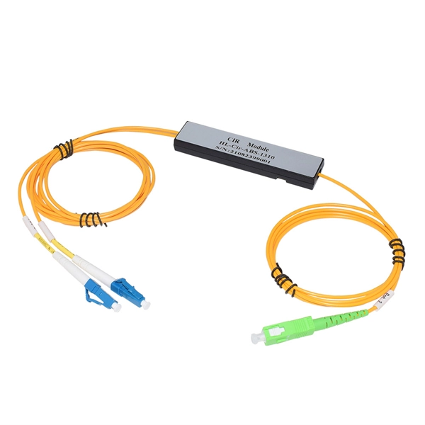
Splitter loss values are "Typical" and include a connector in and out. Use 2×N when two inputs feed the same distribution stage. Common values: 2, 4, 8, 16, 32, 64. 5 dB depending on splitter type. 5 dB. Let's say you have a laser output at 0 dBm (which is 1 milliwatt of optical power). 089 mW (less than a tenth of the. Telcordia and TIA allow a 0. Connector loss is always measured as a mated pair. Ignoring internal imperfections, the ideal insertion loss at each port is given by: In the real world there is always additional excess loss — caused by fusion splices, core alignment, and coupler imperfections inside the. Excess loss is the ratio of the optical power launched at the input port of the splitter to the total optical power measured from all output ports. 2dB/km for single-mode fiber at 1550nm (the primary PON wavelength). A higher split ratio means each output port gets less initial power, limiting how far the signal can travel: A 1:32 splitter divides input power by.
[PDF Version]
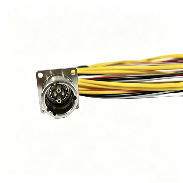
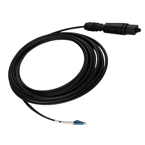
A hybrid fiber optic cable is a composite cable that integrates traditional glass optical fibers for data transmission with copper wires for electrical power. This innovative design eliminates the need to install separate cables for data and power, streamlining complex deployments. In order to do this, they use some very different types of cables. Obviously, these fiber cables need to be resistant to electricity, which can be difficult as many aerial cables contain high tensile steel (HTS) for tensile strength. Optical technology offers suffi ciently significant advantages to power systems environments so that, to date, electricity industries all over the world have either seriously con sidered or indeed utilised a range of optical systems. There are also disad vantages and drawbacks. The difficul ty. I need to know is there a Code and/or Standard prohibiting the placement of Communication fiber in the same conduit as power for Safety reasons. Some primary examples include optical ground wire (OPGW) and all-dielectric self-supporting (ADSS) fiber optic cables, which were both introduced over 30 years ago.
[PDF Version]Contact us for competitive quotes on any of our power communication and smart grid products
Get a Quote