
Return loss meters use two power sensors and fiber couplers to provide a direct measurement of the optical return loss. One sensor measures the optical power reflected back to the instrument while the other.
Compact and portable, our light source and optical power meter tools are essential for testing and verifying insertion losses in fiber links across various networks, including cable TV, enterprise, service.
A class of laboratory power meters has an extended sensitivity, of the order of -110 dBm. This is achieved by using a very small detector and lens combination, and also a mechanical light chopper at typically 270 Hz, so the meter actually measures AC light. This eliminates unavoidable dc electrical drift effects. If the light chopping is synchronized with an appropriate synchronous (or "lock-in") amplifier, further sensitivity gains are achieved. In practice, such instruments usually achieve lower absolute acc.
An optical power meter (OPM) is a device used to measure the power in an optical signal. The term usually refers to a device for testing average power in fiber optic systems. Other general purpose light power measuring devices are usually called radiometers, photometers, laser power meters (can be photodiode sensors or thermopile laser sensors), light meters or lux meters. A typical optic. SensorsThe major types are (Si), (Ge) and (InGaAs). Additionally, these may be used with attenuating elements for high optical power testing, or wavelengt. A typical OPM is linear from about 0 dBm (1 milli Watt) to about -50 dBm (10 nano Watt), although the display range may be larger. Above 0 dBm is considered "high power", and specially adapted units may measure u. Optical Power Meter and accuracy is a contentious issue. The accuracy of most primary reference standards (e.g.,, Length,, etc.) is known to a high accuracy, typically of the orde.
[PDF Version]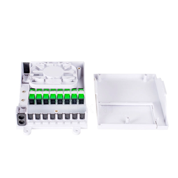
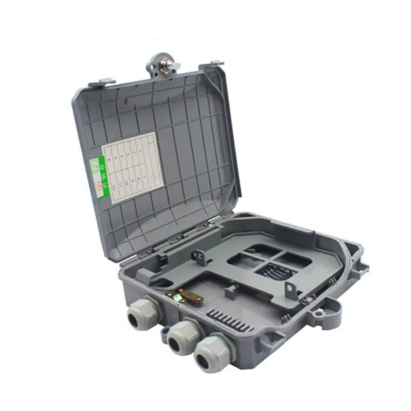
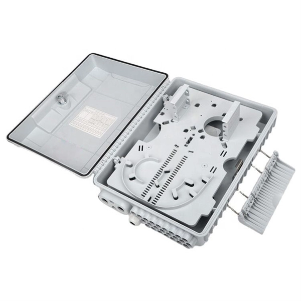
00 per ft depending on terrain, access, and required precision for termination. Total ≈. Typical rates range from $0. Total ≈. CRU provides comprehensive, accurate and up-to-date price assessments and research reports for bare optical fibre across various key regional markets, combined with insights into the factors and events affecting markets. The joint box is made of aluminium alloy and has a maximum c pacity of 240 fibre splices. A pre-moulded neoprene anti-ageing gasket, perfectly inserted in the groove of the cover, provides an excellent sealing entries of the OPGW cables. The anchoring of the joint box. ADSS cable is a non-metallic, self-supporting aerial fiber optic cable designed to be installed on existing poles or power transmission towers without electrical grounding. What Is OPGW Cable? OPGW (Optical Ground Wire) combines optical fibers with a metallic ground wire, serving both lightning. With 19+ years of experience installing fiber-optic cables at over 20,000 locations, we've seen how prices vary based on cable type, project scope, and installation complexity.
[PDF Version]
Splitter loss values are "Typical" and include a connector in and out. Use 2×N when two inputs feed the same distribution stage. Common values: 2, 4, 8, 16, 32, 64. 5 dB depending on splitter type. 5 dB. Let's say you have a laser output at 0 dBm (which is 1 milliwatt of optical power). 089 mW (less than a tenth of the. Telcordia and TIA allow a 0. Connector loss is always measured as a mated pair. Ignoring internal imperfections, the ideal insertion loss at each port is given by: In the real world there is always additional excess loss — caused by fusion splices, core alignment, and coupler imperfections inside the. Excess loss is the ratio of the optical power launched at the input port of the splitter to the total optical power measured from all output ports. 2dB/km for single-mode fiber at 1550nm (the primary PON wavelength). A higher split ratio means each output port gets less initial power, limiting how far the signal can travel: A 1:32 splitter divides input power by.
[PDF Version]Contact us for competitive quotes on any of our power communication and smart grid products
Get a Quote