
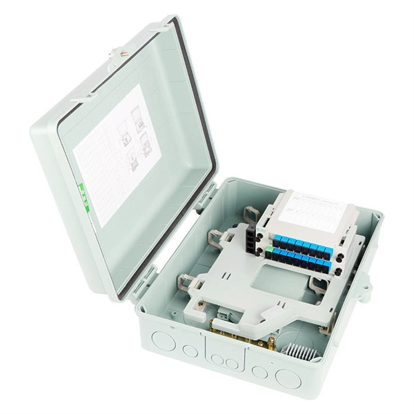
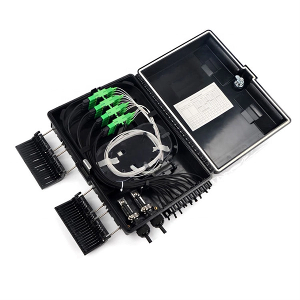
Testing a splitter or other passive fiber optic devices like switches is little different from testing a patchcord or cable plant using the two industry standard tests, OFSTP-14 for double-ended loss (connectors on both ends) or FOTP-171 for single-ended testing. First we should define what these. Splitter loss refers to the reduction in optical power that occurs when a single optical signal is divided among multiple output ports in a fiber optic network. Insertion loss testing of the optical splitter is very important to ensure compliance to the optical parameters of the manufactured. Optical splitters are vital components in fiber optic networks, distributing signals from a single input fiber to multiple output fibers. Here is a table of typical losses for splitters. Signal loss within a system is expressed using the decibel. The CertiFiber® Pro Optical Loss Test Set (OLTS) can be used to check that the loss of a PON Splitter (often referred to in various standards as a non-wavelength-selective or wavelength-selective branching device) to check that it is within the allowed defined limits. The CertiFiber® Pro has an.
[PDF Version]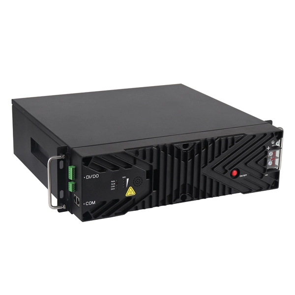
Optical fibers are an integral part of modern communication systems, enabling high-speed data transfer and reliable connectivity. They are thin, transparent strands of glass or plastic used to transmit light signals over long distances. Light acts as a carrier wave and can be modulated to carry information. Fiber is preferred. Recent advancements including coherent detection, optical amplification, and fiber-optic sensing are discussed, along with their impact on future networks.
Optical transceiver interoperability refers to the ability of transceiver modules from different manufacturers to function correctly with a range of networking equipment—switches, routers, servers, and optical transport gear—without compatibility issues. This guide dives deep into the core aspects of optical transceiver compatibility, common. When it comes to the connection between two fiber optic transceivers, the following four factors should be taken into considerations: wavelength, speed, fiber type, and the connection to switches. In a fiber link, the data is transmitted from one end to another, and fiber transceivers are. Several years ago, hyperscale network operators saw an opportunity for coherent Dense Wavelength Division Multiplexing (DWDM) transport optics to plug directly into routers for 400 Gbps Data Center Interconnections (DCIs) with reaches up to 120km. This point-to-point, IP-over-DWDM architecture. MSA (Multi-Source Agreement) standards define the mechanical, electrical, and management interfaces of optical transceivers, enabling multi-vendor interoperability, supply chain flexibility, and large-scale network deployment.
[PDF Version]
BS EN 60794-1-21 is maintained by GEL/86/1. The current release of this standard is: BS EN 60794-1-21:2015+A1:2020 Optical fibre cables. Basic optical cable test procedures. Mechanical tests methods This standard is available from the following sources:The International Electrotechnical Commission (IEC) is the leading global organization that prepares and publishes International Standards for all electrical, electronic and related technologies. The technical content of IEC publications is kept under constant review by the IEC. An objective of this document is to define general requirements and methodology. Listing of all FOA standards FOA Standard FOA-1: Testing Loss of Installed Fiber Optic Cable Plant, (Insertion Loss, TIA OFSTP-14, OFSTP-7, ISO/IEC 61280, ISO/IEC 14763, etc. IEC 60794-1-2:2021 applies to optical fibre cables for use with telecommunications equipment. Electrical properties are specified for optical ground wire (OPGW) and optical phase conductor (OPPC) cables.
[PDF Version]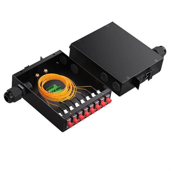
Single-mode fiber (SMF) supports distances up to 40-100+ kilometers for standard applications, while multimode fiber (MMF) is typically limited to 300 meters to 2 kilometers. The actual distance depends on factors including fiber type, wavelength, network equipment, and signal. Network SwitchNetworking DevicesOptics and TransceiversFiber Optic CablesCopper CablesPatch Panels, Cassettes, EnclosuresTesters and ToolsOptical Networking DevicesPower Newsroom Home HPC Data Center Enterprise Network Cabling WDM, OTN, PON Software Hardware Newsroom Home/ Cabling/ Fiber Optic. First is the attenuation of the optical fiber. Attenuation is the weakening of light as it comes in from the transmitting end of the fiber and out of the transmitting end. Many factors cause. Uses a small core (8-10µm) to allow only one light mode, reducing signal attenuation and dispersion.
QSFP-DD is a new module and cage/connector system similar to current QSFP, but with an additional row of contacts providing for an eight lane electrical interface. It is being developed by the QSFP-DD MSA as a key part of the industry's effort to enable high-speed solutions. The Cisco ® QSFP-DD Open Line System (QSFP-DD OLS) is a pluggable optical amplifier module that, together with the channel breakout options (described later), provides a simple yet powerful open. The QSFP-DD OLS is a pluggable open line system solution that can be directly hosted on a Cisco router. 8mm pitch and a dual-mating interface. QSFP-DD extends the use. Supporting the continuing growth in the bandwidth demand and datacenter traffic driven by networking and AI/ML requirements, the QSFP-DD (Double Density) Interconnect System delivers 8 lanes with up to 28 Gbps NRZ or 56 Gbps-PAM4 (up to 400 Gbps aggregate) in a compact footprint that is backward. Get best-in-class optics from legacy GBICs to cutting edge 1. Harness the power of Proline's quality by design. Explore our cutting-edge coding & testing lab.
[PDF Version]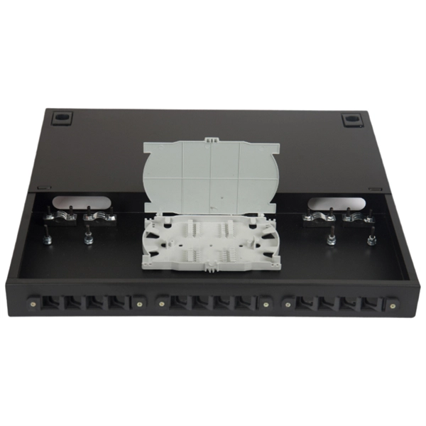
Directional couplers are multiple-waveguide couplers used for codirectional coupling. They can be used in many different applications, including power splitters, optical switches, wavelength filters, and polarization selectors. We consider in this tutorial two-channel directional couplers, which. Mode division multiplexing (MDM) has provided a new trend in high capacity optical transmission systems.
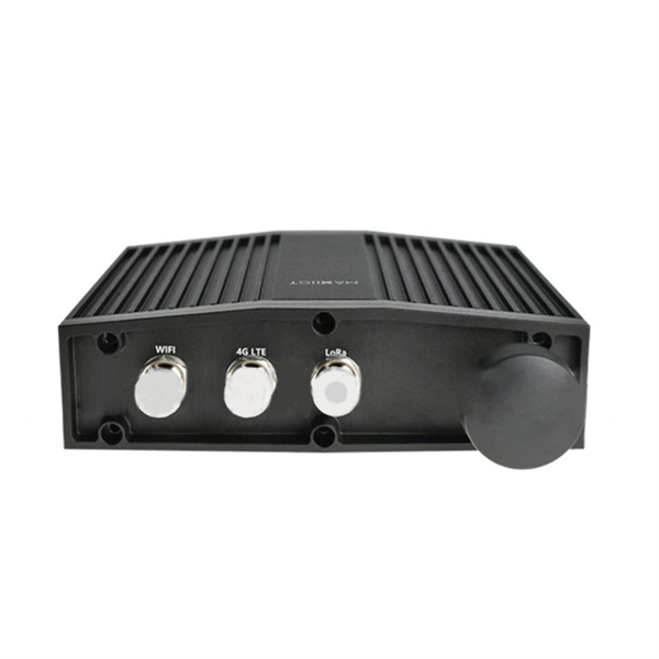
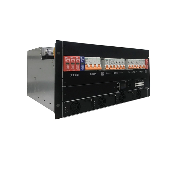
In 4G network, the optical modules used to connect BBU and RRU are mainly Gigabit to 10 Gigabit optical modules; in 5G network, the optical modules used to connect BBU and RRU are mainly 25G rate. RRU is short for remote radio unit. It also provides information about the RRU and its cables. The actual exteriors may be different. Product Versions The following table lists the product versions related to this. Can use 3. 5G rate optical module to complete the multiplexing of low-speed interface services such as 4G at a lower cost; Also used for 40KM long-distance transmission of 10G rate interface (10, 20KM for 1271nm~1371nm window). 25G SFP optical module adopts the wavelength of 850nm, with an operating. The Gamma632 is a 4G&5G dual-mode Remote Radio Unit (RRU) product independently developed by Baicells with independent intellectual property rights.
A simple solution is to combine a Corning USB “A to receptacle-A” USB 3. Optical™ Cables by Corning with a short, off-the-shelf jumper cable that has a USB “A” plug on one side and the particular connector your end device requires on the other. 0 A female port of the AOC Cable. Vielen Dank für den Kauf dieses Optischen USB 3. Es unterstützt größere Distanzen als herkömmliche Kupferkabel, ist deutlich flexibler und leichter und daher optimal. A workaround would be to connect the USB 3. Once connected, check the Windows Device Manager to verify the devices that have been successfully connected through the device. The USB active optical cables are designed to be compliant with SuperSpeed USB and SuperSpeed+ USB electrical specifications, offering seamless interoperability between existing USB 3. 1 hosts, hubs and devices, ensuring a trouble-free plug-and-play experience. The USB AOC address the. Connect the USC-CC32 Type C device connector to the USB Hub.
[PDF Version]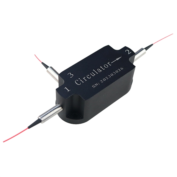
Once you've selected your pigtail, the bare fiber end needs to be permanently joined to the incoming cable fiber. The right choice depends on your performance requirements, budget, and the volume of. A fiber optic pigtail is a short length of optical fiber cable with a factory-terminated connector on one end and a bare, exposed fiber on the other. This blog compares the two in clear, practical terms.
Contact us for competitive quotes on any of our power communication and smart grid products
Get a Quote