
An optical module primarily consists of optoelectronic devices, functional circuits, and optical interfaces. The core optoelectronic devices include the Transmitter Optical Sub-Assembly (TOSA) and the Receiver Optical Sub-Assembly (ROSA), with lasers and detectors forming the core. Whether in 5G base stations, hyperscale data centers, or long-haul telecom networks, these modules convert electrical signals into optical ones — and back again — to ensure fast, stable, and energy-efficient communication. Through this article, you will know the details of the components and structure of the optical transceiver modules.
This paper describes a newly developed butt joint type hollow-core fiber connector with protected fiber ends. It can typically realize nearly 0.5-dB insertion and 45-dB return loss without physical contact. I.
A novel five-tube nested double C-type single-polarization hollow-core anti-resonant fiber (HC-ARF) is proposed for single-polarization single-mode, ultra-low loss, and broadband characteristics. Differen.
Optical Core Alignment (also called “Profile Alignment”), an optical alignment technique, is used by many models of fusion splicers. The two fibers are illuminated from two directions, 90 degrees apart. Fusion splicing is the process of fusing or welding two fibers together usually by an electric arc. The goal is to fuse the two fibers together in such a way that light passing through the fibers is not scattered or reflected back by the splice, and so that the splice and the region surrounding it are almost as strong as the. Fibre optic splicing trays are an essential part of manipulating and ordering optical fibers inside a network structure. Since the need for higher data rates and effective communication gets more robust, the utilization of optical fibers has become increasingly widespread across multiple spheres of. Corning splice trays use proven designs and fiber organization technology to provide optimum physical protection for fusion and mechanical splicing methods. The trays are engineered for use with indoor or outdoor splice hardware with both loose tube and tight-buffered optical cable designs.
[PDF Version]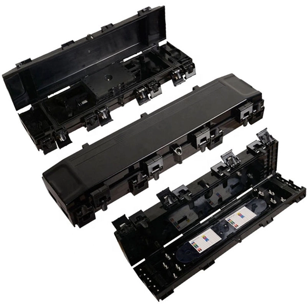
The global optical modules market was valued at $14. 8 billion in 2025 and is projected to reach $39. 5% during the forecast period from 2026 to 2034. 8% (2025-2031), driven by critical product segments and diverse end‑use applications, while evolving U. 0% during the forecast period 2025-2032 MARKET INSIGHTS The global Optical Module Chip Market size was valued at US$ 823 million in 2024 and is projected to reach. Optical module demand is being pulled in two directions at once, faster bandwidth for dense networks and tighter constraints on power, security, and lead times. 1 billion by 2025 and 35 percent of manufacturers reporting lead times beyond 12 weeks, the. Global Optical Modules Market Size By Product Type (Transceivers, Transponders), By Technology Type (Single-Mode Fiber (SMF), Multi-Mode Fiber (MMF)), By Application (Telecommunications, Data Centers), By Data Rate (10 Gbps, 25 Gbps), By Form Factor (SFP (Small Form-Factor Pluggable), SFP+. The global optical modules market was valued at $14.
[PDF Version]
When fiber cables sustain damage, specialized repair techniques help restore connectivity and maintain data integrity. As we move deeper into 2025, with global fiber deployments accelerating at a 10. When it comes to ensuring nice network experiences for users, the condition of a fiber. While a cut or damaged fiber optic cable can temporarily take your network down, it is possible to quickly fix the cable with the right tools. This wikiHow article will teach you how to splice a cut fiber optic cable back together with a fiber optic stripper and cutter and a fiber optic crimper.
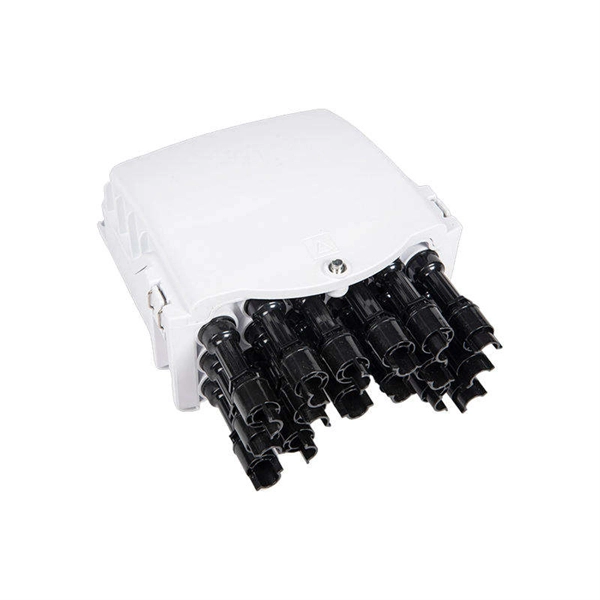
With its innovative design and robust features, this 48 core fiber distribution box is a cost-effective and reliable choice for optimizing fiber optic networks in diverse settings. Find more 1420, 153713 and 1537 products. Enjoy ✓Free Shipping Worldwide! ✓Limited Time Sale ✓Easy Return. We offer optical distribution frame in different size, such as 12 core, 24 core, 48 core, 72 core, 96 core, 144 core, SC, FC, LC adapter options are available. Inspect the quality carefully of your goods. Make documents for you to do custom clearance,packing list and commercial invoice. Optical Cable, 48 Port Terminal Box, Fiber Optic Rack, Fiber Optic Distribution Frame, 48 Core Fused Fiber Optic Box, SC Empty Box48 core SC/ 96 core LC fiber distribution splicing for the last mile installation The 48 Core fiber distribution box features a two-panel flip-up design, providing a separate working area for effortless management by the installer.
[PDF Version]
The bend radius of fiber cables is critical for maintaining high performance and longevity. During installation under tension, maintain a minimum bend radius of 20 times the cable's outer diameter, while post-installation requires a minimum long-term bend radius of 10 times the. Fiber optic cable bend radius is a critical mechanical parameter that determines how sharply a cable can be bent without risking microbending, macrobending, signal loss, or long-term structural fatigue. It is measured from the inside of the bend, not the outer curve. Installers must understand these specifications and know how to install cables without. Fiber optic cables are designed to withstand some bending, but excessive bends can physically damage the glass fiber or cause significant signal loss.
Contact us for competitive quotes on any of our power communication and smart grid products
Get a Quote