
An optical line termination (OLT), also called an optical line terminal, is a device which serves as the service provider endpoint of a passive optical network. It provides two main functions: to perform conversion between the electrical signals used by the service provider's equipment and the fiber optic signals used by the passive optical network.to coordinate the multiplexing between the conversion. FeaturesOLTs include the following features: • A downstream frame processing means for receiving and churning an cell to generate a downstream frame, and converting a parallel dat. Most vendors integrate an entire fiber optic management system for ISPs to manage OLTs as well as client ONTs and as such are not interoperable. • • BT-PON.
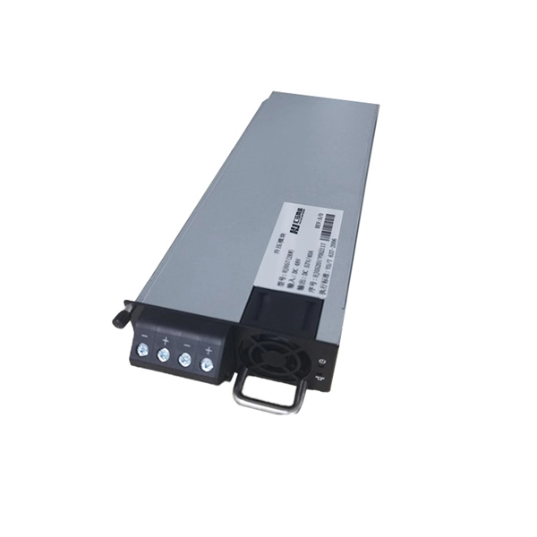
An optical module is a typically hot-pluggable optical transceiver used in high-bandwidth data communications applications. Optical modules typically have an electrical interface on the side that connects to the inside of the system and an optical interface on the side that connects to the outside world through a fiber optic cable. The form factor and electrical interface are often specified by an interested group using a (MSA). Optical modules can either plug into a front pa.
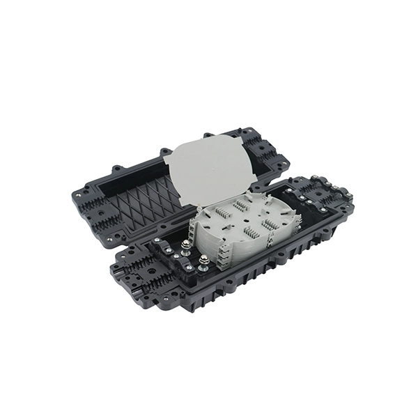
There are multiple methods to use for attaching fiber optic modules to an electro-optics assembly, and may include: soldering, conductive adhesives, or mechanical assembly. The Printed Circuit Board (PCB) at the heart of these modules is no longer a simple substrate but a highly engineered system. Designing and producing these complex PCBs presents formidable challenges, requiring a convergence of disciplines—from high-frequency signal integrity and advanced thermal. Extend Routed Optical Networking use cases to regional and ultra-long-haul DWDM applications. Transmit 400G wavelengths up to 120 km with coherent ZR and enable long-haul transmission with OpenZR+. They protect and organize the sensitive connection points between optical fibres and play a decisive role in the quality, reliability and ease of maintenance of the entire network., two fiber connectors) such that light can reliably pass from one to the other with minimal insertion loss and maximum return loss. By following these detailed steps, the installation of your Fiber Splice Closure will be secure, organized, and maintained, ensuring high performance and longevity of your fiber optic network.
[PDF Version]
Electrostatic discharge can damage the internal laser driver and digital signal processors. Follow these ESD protection practices: Always wear an ESD wrist strap grounded to an antistatic mat. Use ESD-safe containers for storage and. Common Problems Encountered in Optical Module Applications In real-world deployments, It failures generally fall into several key categories. Most issues are not isolated but result from compatibility, environment, or improper operation. The exact cost of ESD induced failures to the Electronics Industry is difficult to calculate since many of. The number of failures caused by electrostatic discharges (ESD) has been increasing for some time now. The paper will give an overview about possible causes for ESD. This guide from ESOPTIC provides practical tips on optical transceiver insertion, removal, cleaning, and ESD protection, ensuring that your modules operate efficiently and safely. Before installing an optical transceiver, always make sure the device is powered down (unless hot-swapping is. 2022-07-01Assigned to JPMORGAN CHASE BANK, N., AS COLLATERAL AGENTSECURITY INTEREST (SEE DOCUMENT FOR DETAILS)., II-VI INCORPORATED, II-VI PHOTONICS (US), INC.
[PDF Version]
In order to save power within the module, optical modules have been made that used the digital interface definition, such as the CEI, but without retiming the signals within the module.OverviewAn optical module is a typically hot-pluggable optical transceiver used in high-bandwidth data communications applications. Optical modules typically have an electrical interface on the side that connects t. There have been multiple variants of the electrical interface of optical modules that have been used over the years. The earliest forms of optical modules had an analog electrical interface. In the transmit dir.
Contact us for competitive quotes on any of our power communication and smart grid products
Get a Quote