
While optical power meters are the primary power measurement instrument, optical loss test sets (OLTSs) and optical time domain reflectometers (OTDRs) also measure power in testing loss. TIA standard test FOTP-95 covers the measurement of optical power. This type of testing is the most accurate testing available and is the most accurate characterization of the fiber optic system's apability. Testing with. After fiber optic cables are installed, spliced and terminated, they must be tested. An Optical Power Meter and Laser Light Source will be used to measure power loss on each completed ring or distribution span to verify continuity between fibers (no fibers incorrectly spliced.
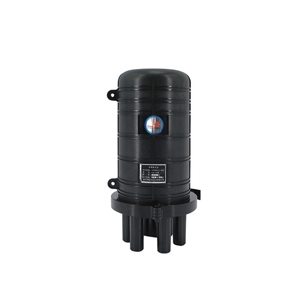
Fusion couplers, made by melting a section of twisted fibers, offer the lowest insertion loss (~0. 3 dB) and highest power handling, with a limited wavelength bandwidth of ±40 nm and polarization extinction ratio below 23 dB. Optical splitters, encompassing FBT (Fused Biconical Taper) couplers and PLC (Planar Lightwave Circuit) splitters, are prevalent passive optical devices designed to divide fiber optic light into multiple segments based on a specified ratio. T PON standards such as GPON, XGS-PON and new 25 and 50G standards. We offer a full line of fiber optic couplers and splitters supporting SM, MM, PM, large core, and double-clad fibers across 300–2000 nm, with power handling up to 100 W and operating temperatures up to 300°C. Three fabrication methods are employed: fusion, micro-optics, and planar lightwave circuit. Carrier-grade standard insert type 1-4 optical splitter, low insertion loss, uniform light splitting 2. Uniform light splitting and stable transmission using high-quality transmission.
[PDF Version]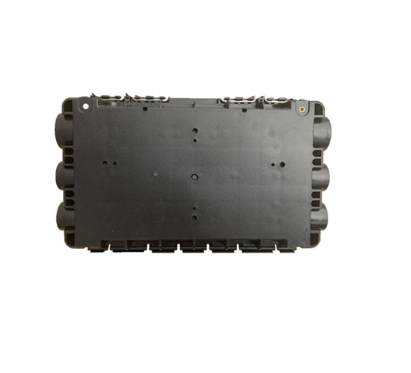
In this blog post, we'll take a deep dive into the key performance tests for fiber optic patch cords — polarity verification, insertion loss and return loss measurement, 3D interferometric endface metrology, and endface inspection — along with the relevant standards . In this blog post, we'll take a deep dive into the key performance tests for fiber optic patch cords — polarity verification, insertion loss and return loss measurement, 3D interferometric endface metrology, and endface inspection — along with the relevant standards . One of the key performance indicators of a fibre optic patch cord is its insertion loss. Insertion loss refers to the reduction in power density (signal) that occurs when a signal is transmitted through the patch cord. This article explains their concepts, standards, testing methods, and FiberMania's quality assurance workflow to ensure optimal network performance. Fiber optic patch cords are crucial components in. Insertion Loss (IL) is one of the most fundamental performance indicators in fiber optic networks.
[PDF Version]
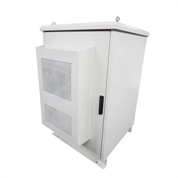
Generally speaking, the size of a one meter standard network cabinet is 600mm * 600mm * 1000mm. The picture shows a lot of outboard gear built into the cabinets, which completely follows the 19-inch rack standard. A 19-inch rack is a standardized frame or enclosure for mounting multiple electronic equipment modules. Upon completion of the installation, a third party field verification firm will independently verify. Shop durable network cabinets built from cold-rolled steel. Secure your IT and AV equipment with lockable glass doors and side panels. Rack height is measured in rack units (U) — 1U = 1. Common sizes: 42U, 48U, and compact options like 22U–27U. Standard width is 19 inches (EIA-310 compliant), while outer widths vary (e. Rack depth matters for. Network cabinets are enclosed systems designed to securely store, organize, and protect networking and IT equipment such as switches, routers, patch panels, servers, power strips, and cable management components.
[PDF Version]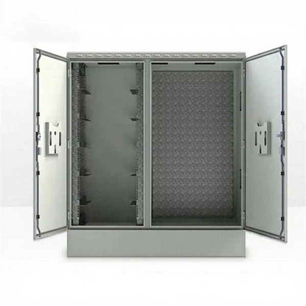
This project describes the complete process of designing a reliable IEC 62056‑21 optical smart‑meter probe, covering hardware engineering, infrared communication tuning, PCB design, 3D‑printed enclosure development, ESP32 integration, and full ESPHome support. This project involves thermal dissipation, peltier cells, a candle, Arduino, ADCs and a lot more! You will learn a lot, the same as I did by making this experiment. Once I have all the data, I will finish the controller PCB as well. As you can see in the video, we. To build DIY optical power meter with standard SFP module and Arduino - Can measure optical power in dbm and watt - Can Enable/Disable TX power output (laser source) - Can debug via UART And Arduino Library - a lib for SFP/DDM interfacing (not only optical sfp transceiver - to interface and. LPM is a laser power meter used for reading the output power of a laser. The circuit includes Arduino Nano board (Board1), 16×2 LCD display LCD1, NPN transistor BC547 (T1), and.
[PDF Version]
To use a power meter for fiber optic testing, always clean connectors first with lint-free wipes or click-to-clean tools. Select the correct wavelength and set your reference. You measure optical power in dBm or insertion loss in dB. Consistent procedures ensure accuracy. Verify light travels from. How to Use Optical Power Meter TR-504 | Optical Power Meter Working| Testing OPM, VFL, RJ45 | TRICOM. Because all of those devices rely on light, they use it to ensure those devices are functioning. power across any given fiber. This document will serve as an overview of the major features and functions of the device and will offer tips for trouble shooting com on issues in optical networks.
Contact us for competitive quotes on any of our power communication and smart grid products
Get a Quote