
How PI Test Works: The PI test involves applying a DC voltage to the insulator and measuring resistance at 1 minute and 10 minutes. Current Components: During the test, currents through the insulator include capacitive, conductive, surface leakage, and polarization . Polarity testing is one of the tests that are required for initial testing of the installation under IEC 60364 standard. This test will verify that all the switches installed in the system are connected in current carrying conductor and not in neutral. What Is Polarity in Electrical Installations? It refers to the direction of current flow in an. In the intricate world of electrical work, ensuring the correct polarity of alternating current (AC) is not just a matter of technical detail; it's a fundamental aspect of safety and functionality. By performing this test, you prevent electric shocks and protect sensitive equipment from damage caused by reversed wiring.
[PDF Version]
A relay protection tester is a device used to test and verify the performance of relay protection devices in power systems. This happens because the main function of protection devices is related to operation under fault conditions so these devices cannot be tested under normal operating conditions. Megger's smart relay testing solutions and expert support help you validate protection performance, improve system reliability, and ensure continuity of power across your network. Ensure protection systems operate correctly. The main function of a protection relay is to detect primary-sided faults or overloads as rapidly as possible and to selectively isolate the affected assets or parts of the grid from the rest of the grid or substation using circuit breakers.
This is a test to check the maximum length of time that the protection relay can withstand an interruption in the auxiliary supply without de-energizing, e. switching off, and that when this time is surpassed and it does transiently switch off, that no maloperation happens. Since the basic function of a protection relay is to correctly function under abnormal. Verify instantaneous pickup setting for motor protection relay blocks motor starting current but clears high-level faults Relay calibration drift causes cascading failures: a relay set to operate in 0. 8 seconds allows fault damage to propagate upstream, tripping feeder. Megger's smart relay testing solutions and expert support help you validate protection performance, improve system reliability, and ensure continuity of power across your network.
Connect a visible light source (such as a fiber optic flashlight) to one end of the cable. Take an LED flashlight and shine the light into one of the fiber. The three standard methods for testing fiber optic cabling are a visible light source, power meter and light source, and optical time domain reflectometer (OTDR). Because fiber optic transmissions work in the infrared portion. FiberLert is a fast, accurate, and safe non-contact solution for verifying fiber activity, polarity, and connectivity. First, aim your smartphone camera at the connector; most phone sensors detect the otherwise invisible 85.
Fiber optic cable testing can be categorized based on the type of test being conducted: End-to-End Testing: Verifies light transmission capability and signal integrity over the entire length of the cable. The performance and reliability of these networks depend on the quality of the fiber optic cables and the precision of their installation. As the components like fiber, connectors, splices, LED or laser sources, detectors and receivers are being developed, testing confirms their performance specifications and helps. This Applications Engineering Note (AEN 135) explains and recommends standard measurement methods for characterizing optical fiber system performance. A single speck of dust on a connector can cause significant signal loss.
The Divot® Bare Fiber Adapter (Tester) accepts cleaved and non-cleaved fiber, requires only 3/4” of bare fiber exposed and has a typical insertion loss of less than 0. No messy gel applicators or reservoirs to fill. Simply strip your fiber and insert. Availability: In. The FiberConnect is the ultimate time saving solution for coupling unterminated fiber or optical components to test equipment. By allowing the user to perform optical measurements without terminating, which requires additional equipment and procedures, test time can be significantly reduced over. FC Bare fiber adapter is a very efficient media to connect bare fiber to fiber optic device, it usually used in installation to test links. Quickly test unterminated singlemode. If you need to test a bare fiber, splicing a pigtail or placing a connector is not the most time or cost effective means of conducting a test. Bare fiber and mating adapters make testing bare or dissimilar fiber ferrules quick and easy.
[PDF Version]
The IEC has published a new standard for the testing of fibre optic cabling. IEC 61280-4-5 provides test methods to measure the attenuation of installed multimode and single-mode optical fibre cabling plant as well as the determination of their polarity and length. Fiber optic testing of a newly installed system not only verifies that the system meets its design requirements, but also creates a performance baseline for all future testing and troubleshooting of t at system. Corning recommends that all fiber optic systems be tested to a minimum set. for installing electrical products and systems. NEIS® are intended to be referenced in contrac documents for electrical construction ation or liability to users of this publication. Lower attenuation means less signal loss over distance. Patch cords and jumper cables must meet stricter performance requirements because connectors. ANSI/TIA‑568.
[PDF Version]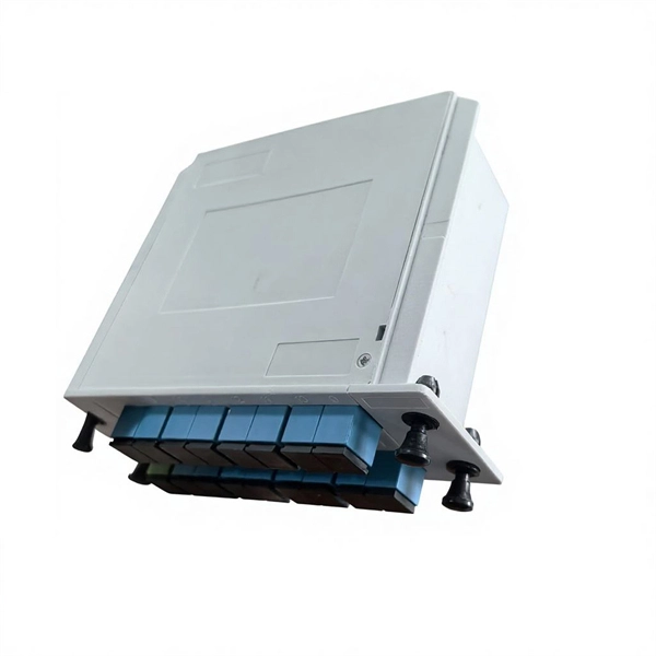
Explore 74 top manufacturers and suppliers of Optical Testing Instruments in our comprehensive photonics buyers' guide. An optical testing instrument is a device or system used to evaluate and measure the performance, quality, and characteristics of optical components . MEETOPTICS is the world's largest database of photonics products and custom solutions, covering the entire supply chain from raw materials to software and laboratory equipment. Optical. 3D Interconnect Designer provides a flexible modeling and optimization environment for any advanced interconnect structure, including chiplets, stacked die, packages, and PCBs. Emulate every part of your data center infrastructure. Use 25+ X-Series. Automated testing device for multiple optical test subjects or various optical performance parameters. Introduction to the 2023 Physics Nobel Prize - First Meet with Asecond Laser! Industry 4. It combines technical advancements and usability improvements with new features to provide top-end, flexible solutions.
[PDF Version]
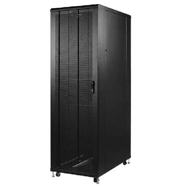
Here's a basic guide on how to measure ground resistance and test the grounding system's proper functionality using a multimeter: According to NEC 250. If you're setting up a server rack, one of the most important things to consider is proper server rack grounding. Without it, you risk electrical shock, equipment. Bonding (or grounding) is a system of protective measures, which is implemented to prevent electric shocks when touching metal parts of energy-powered equipment. The whole structure consists of a metal circuit, a protect bus, and a ground wire. 1100, TIA-942, how to apply the information found in. How to Check Earthing and Measure Ground Resistance using a Multimeter? Measuring ground resistance using a multimeter is generally not as accurate as using specialized ground resistance testers, but it can provide a rough estimate. A properly grounded rack mitigates the risks associated with electrostatic discharge (ESD), transient voltage surges, and fault currents.
[PDF Version]Not grounding a grounded rack can result in various risks, including electrostatic discharge (ESD) that can damage sensitive electronic components,...
To determine if your server rack is properly grounded, you can use an electrical multimeter to measure resistance between the rack's ground connect...
When connecting servers and equipment to a grounded rack, ensure that grounding cables are not overly stretched or under strain, avoid daisy-chaini...
Yes, there are different grounding methods for server racks. These methods include using grounding bars, grounding strips, and direct grounding cab...
There are industry standards and regulations for server rack grounding, often set by international and regional bodies. In the U.S., for instance,...

Testing a splitter or other passive fiber optic devices like switches is little different from testing a patchcord or cable plant using the two industry standard tests, OFSTP-14 for double-ended loss (connectors on both ends) or FOTP-171 for single-ended testing. A passive device used to split or combine signals on fiber optics may be called a splitter, combiner or coupler, but splitter is the most common term. 6inch color touch screen, button/touch dual operation; Internal integration of eight major functional modules, multi-functional. As fiber deployments become commonplace, network owners and technicians are paying more attention to the two crucial devices for testing fiber optical cables: the Optical Loss Test Set (OLTS) and the Optical Time Domain Reflectometer (OTDR). An OLTS provides the most accurate insertion loss. The CertiFiber® Pro Optical Loss Test Set (OLTS) can be used to check that the loss of a PON Splitter (often referred to in various standards as a non-wavelength-selective or wavelength-selective branching device) to check that it is within the allowed defined limits. To view the full specifications, download the spec sheet below.
[PDF Version]Contact us for competitive quotes on any of our power communication and smart grid products
Get a Quote