
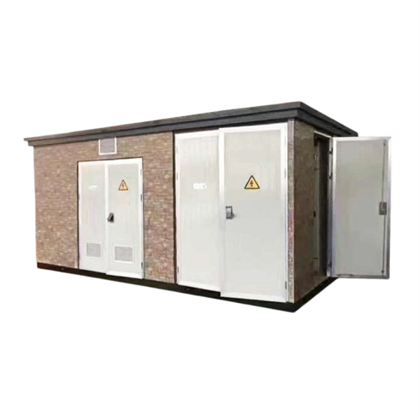
Learn professional control panel wiring standards, including cabinet layout, grounding rules, wiring principles, common mistakes, EMI prevention, and best practices for building clean and reliable industrial control cabinets. It is important that wiring be held together neatly using cable ties to ensure that everything is in an organized and neat order. It is advisable for everything to be tightly connected and there should. This article outlines the essential considerations for designing a high-quality electrical control cabinet, from material selection to wiring methods📝. Designing the. DIN rails and wiring ducts must be arranged logically: General structure: 3. Wiring Principles Signal cables should be: 4. Sure, the specs of the wire itself matter (and we'll cover them below), but layout and safety planning are arguably even more important.
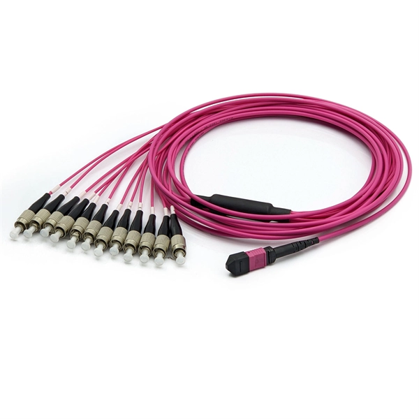
The fiber distribution box, also known as the optical fiber termination box, is a critical component in fiber optic networks. It acts as a central point for terminating, splicing, and distributing these cables. Fiber distribution box is suitable for the wiring connection of optical cable and optical communication equipment, through the adapter in the wiring box, the optical jumper leads the optical signal, and realizes the optical wiring function. OTRANS strives to provide you with professional, reliable. Check each product page for other buying options. In addition, the drawer structure also facilitates high-density wiring and good cable management.
The optical receiver adds two types of noise namely thermal noise and shot noise. This application note provides an in-depth analysis of the complete receiver optical sensitivity and the potential power penalties related to the accumulation of random noise and inter-symbol interference (ISI) in both amplitude and timing. Ultimately, the noise influence on the signal will determine the system sensitivity. The challenge is to find a way to determine the. In the design of an optical receiver, it is vital that the module is capable of converting and shaping the optical signal while meeting or surpassing the maximum BER.
Contact us for competitive quotes on any of our power communication and smart grid products
Get a Quote