
Whether you're working on an industrial, commercial, or data center project, this step-by-step guide will help you get it done safely and efficiently. 🔧 What You'll Learn: Preparing the installation area and measuring for accuracy Installing mounting brackets and ensuring proper. Wire Mesh Cable Tray Installation Guide | Step-by-Step Tutorial Welcome to our wire mesh cable tray installation tutorial! In this video, we'll walk you through the entire process of installing a wire mesh cable tray system, from preparation to completion. Known for their open design, these trays allow for excellent ventilation, easy cable access, and simplified installation. These cable trays are lined with wire mesh to route and support small diameter cable, such as data communication cable. The mesh is smooth to prevent cutting or abrasion to the cable during. Cable trays resemble ladders that are open. They can sustain heavy power cables. You do not need to pull anything. The wire mesh (or basket) trays are. Efficient cable management is critical for modern infrastructure, whether it's in industrial facilities, commercial buildings, or data centers. This guide will walk you through.
[PDF Version]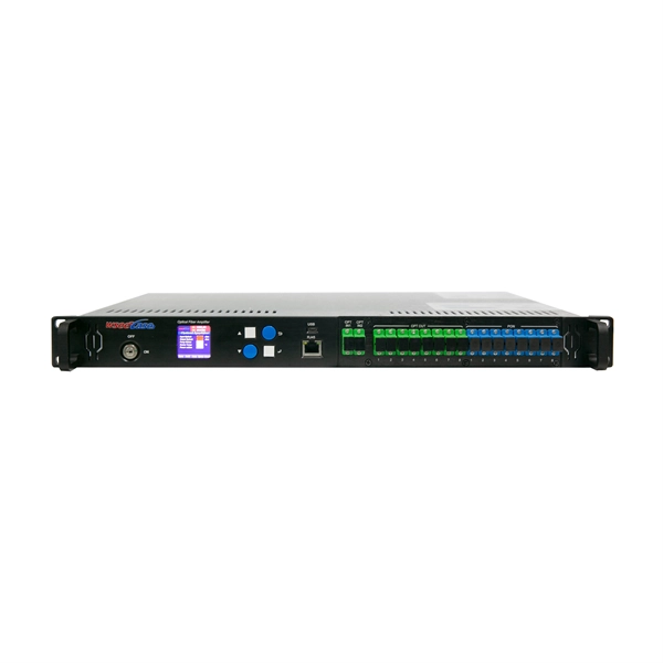
Check for proper IP/NEMA ratings and material quality. Ensure safe placement: install in dry, accessible areas with good ventilation and at appropriate height (typically ~1. Practice good wiring: secure grounding, neat cable management, proper insulation, and correct wire. Strictly speaking, the word “Distribution Box (D-box)” can refer to two categories: electrical distribution boxes and septic tank distribution boxes. This article mainly talks about the first one. Whether it is residential buildings, commercial facilities or industrial sites, the. In the USA and Canada (following NEC and CEC), distribution transformers typically receive 4. 2 kV on the primary side and step it down to 120V single-phase and 120/240V split-phase for residential applications. The primary side of the distribution transformer is supplied by two conductors. Material preparation: Prepare the required circuit breakers, wires, wiring ties and other materials, and ensure that they meet the design drawings and installation requirements.
[PDF Version]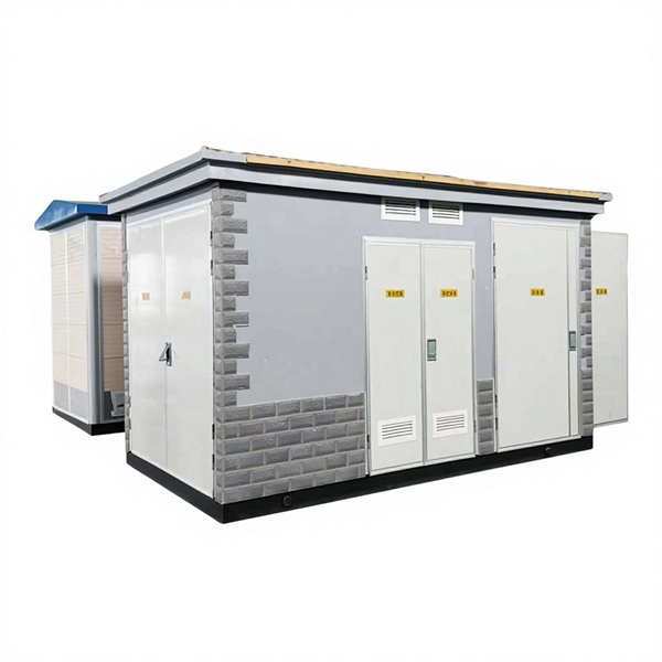
3ad link aggregation enables you to group Ethernet interfaces to form a single link layer interface, also known as a link aggregation group (LAG) or bundle. An aggregation switch is a network device that consolidates traffic from multiple access switches, wireless access points, or other edge devices and forwards it to core switches or routers. The LAG balances. This chapter covers the design recommendations for a data center design deployment consisting of a Cisco Nexus® 7000 Series Switch at the aggregation layer and a Cisco Nexus 5000 Series Switch at the access layer. By design, it therefore provides resiliency because it will always be deployed in pairs of switches and comes with a recommendation to deploy only dual hot swappable power supplies and redundant fans in each switch to. Switch aggregation, also known as link aggregation or trunking, is a method used in computer networking to combine (aggregate) multiple network connections in parallel.
[PDF Version]
Fibre Channel (FC) is a data transmission protocol used in a storage area network (SAN). An FC SAN provides an external storage environment for servers by using the FC protocol suite. To support this architecture, each local FC fabric configured on. This document discusses these considerations and provides operational guidelines on how to deploy and implement an FCoE solution with Cisco Nexus 5000 Series switches. The VF_Port can work properly only when the VF_Port is bound to a physical Ethernet interface.
FC used throughout all applications for Fibre Channel infrastructure and devices, including edge and ISL interconnects. Each speed maintains backward compatibility at least two previous generations (I.e., 32GFC backward compatible to 16GFC and 8GFC)OverviewFibre Channel (FC) is a high-speed data transfer protocol providing in-order, lossless delivery of raw block data. Fibre Channel is primarily used to connect to in (SAN) in co. When the technology was originally devised, it ran over optical fiber cables only and, as such, was called "Fiber Channel". Later, the ability to run over copper cabling was added to the specification. In order to avoid confu.
An optical transport network (OTN) is a digital wrapper that encapsulates frames of data, to allow multiple data sources to be sent on the same channel. This creates an optical for each client signal. defines an optical transport network as a set of optical network elements (ONE) connected by links, able to provide functionality of transport, multiplexing.
Contact us for competitive quotes on any of our power communication and smart grid products
Get a Quote