
Q2: How much signal loss can I expect from an 8-way RF splitter? A: The theoretical signal loss (insertion loss) for an ideal 8-way RF splitter is approximately 9 dB. In practice, the actual loss is usually slightly higher due to internal losses in the splitter. Let's say you have a laser output at 0 dBm (which is 1 milliwatt of optical power). If you use a 1×8 splitter with ~10. 5. Using any garden-variety 8-way splitter to distribute signal will mean that the output signal is only about 3. 6% as strong as the input signal. However, it does not account for the insertion loss caused by the splitter's internal components, such. Optical insertion loss refers to the signal loss resulting from the insertion of components such as connectors or splices in an optical fiber system.
The normal recommendation for fiber optic cable is the minimum bend radius under tension during pulling is 20 times the diameter of the cable (d). 679. This Applications Engineering Note (AE Note) addresses application and selection considerations for improved bend performance optical fibers (IBP fibers). IBP fibers offer operational improvements where fibers or cables are subjected to acute bends. While installers are aware of the fundamental importance of minimum bend radii, they often lack the practical know-how to. Fiber optic cable bend radius is a critical mechanical parameter that determines how sharply a cable can be bent without risking microbending, macrobending, signal loss, or long-term structural fatigue.
It consists of three wires: the positive (+) wire, the negative (-) wire, and the sensor wire. The sensor wire is used by the motherboard to monitor the fan speed. Tripp Lite rack fans are designed for the needs of the IT department. They install quickly. Did you get yourself standard 12V PC fans or an actual rack cooling product (example: https://a. Each wire in. How to distinguish the positive and negative terminals of the frameless cooling fan? The proper installation and use of frameless cooling fans, including the separation of positive and negative terminals, is crucial to the heat dissipation effect and stability of the equipment. Speed Control Wire (Tachometer): Found on. That rack (or racks) serves as the consolidation point for your network and can be quite a bit of fun to plan out for your install. That same rack can become the source of frustration and the stuff of nightmares if you plan it all wrong, however! In this blog, we will cover: What is a server and/or.
[PDF Version]
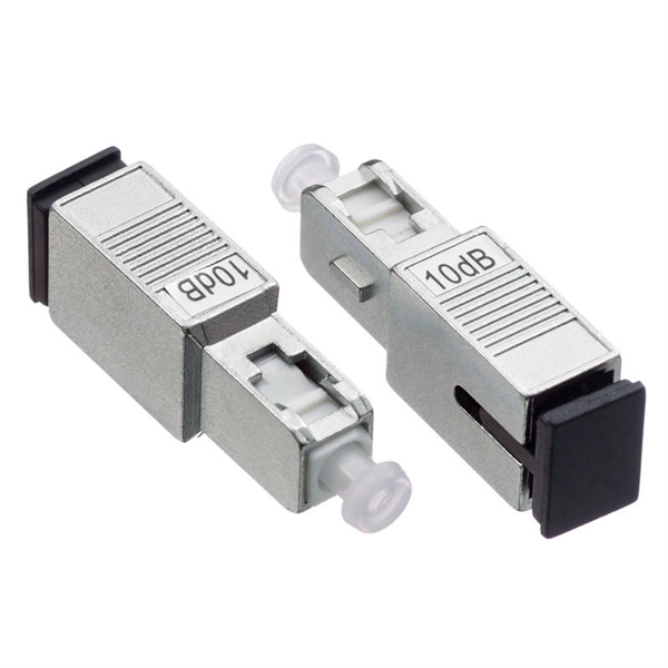
Fusion couplers, made by melting a section of twisted fibers, offer the lowest insertion loss (~0. 3 dB) and highest power handling, with a limited wavelength bandwidth of ±40 nm and polarization extinction ratio below 23 dB. Optical splitters, encompassing FBT (Fused Biconical Taper) couplers and PLC (Planar Lightwave Circuit) splitters, are prevalent passive optical devices designed to divide fiber optic light into multiple segments based on a specified ratio. T PON standards such as GPON, XGS-PON and new 25 and 50G standards. We offer a full line of fiber optic couplers and splitters supporting SM, MM, PM, large core, and double-clad fibers across 300–2000 nm, with power handling up to 100 W and operating temperatures up to 300°C. Three fabrication methods are employed: fusion, micro-optics, and planar lightwave circuit. Carrier-grade standard insert type 1-4 optical splitter, low insertion loss, uniform light splitting 2. Uniform light splitting and stable transmission using high-quality transmission.
[PDF Version]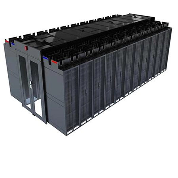
Modern fiber optic networks usually keep splice loss low, as shown below: You should know that each splice can add 0. If losses add up, you may face poor signal quality and need more maintenance. This helps the network. Fiber optic pigtails are used to connect fiber optic cables using fusion or mechanical splicing. The estimate, called a "loss budget" is calculated using typical component losses for. Fiber splice loss measures how much signal drops when you join two fiber ends. The total loss in decibels at the fusion splice is given by the following equation, where Pin is the total power incident on the fusion splice and Ptrans is the. One problem I continue to see is unexpected high loss during spicing between exchange-to-exchange network, particularly in the feeder and backbone segments, which can seriously impact the performance of the PON networks. While drop fibers from the splitter to end users often receive less attention.
[PDF Version]
A uni-directional test will be conducted on all pigtail splices with no greater than a. 8 dB after 5 repeated attempts results in the replacement and re-splicing of that pigtail. dB loss in fiber optics is the reduction in light signal strength as it travels through a fiber cable, measured in decibels. The connector end is polished and tested under factory conditions, ensuring low insertion loss and high return loss. 1 dB per 100 feet (30 m) for 850 nm, 0. For singlemode fiber, the loss is about 0. While some loss is expected, excessive or unexpected loss can lead to poor performance, network downtime, and signal failure. Recognizing what constitutes too much loss is essential. At TREND Networks, we are frequently asked how much loss is allowed when conducting testing on fibre optic cabling.
Quick answer: Industry acceptance threshold for a single fusion splice is 0. 1 dB should be re-done before sealing. Acceptable dB loss for fiber depends on the component you're measuring: a single mated connector pair should lose no more than 0. 5 dB per kilometer depending on the type and wavelength. The total. To be able to judge whether a fiber optic cable plant is good, one does a insertion loss test with a light source and power meter and compares that to an estimate of what is a reasonable loss for that cable plant. The primary contributors to measured splice loss are fiber material and design factors that. Splice loss refers to the part of the optical power that is not transmitted through the splice and is radiated out of the fibre. The total loss in decibels at the fusion splice is given by the following equation, where Pin is the total power incident on the fusion splice and Ptrans is the. When using a fusion splicer, the typical splice loss is usually between 0. However, various factors, such as fibre cleanliness, core. Results from a National Electronics Manufacturing Initiative (NEMI) project, formed to improve aspects of fiber optic fusion splicing, are reported.
[PDF Version]
To perform an OTDR test correctly, you must: 1. Set core parameters (Wavelength, Distance, Pulse Width); 4. Run the test (Real-time or Average); 5. OTDR (Optical Time Domain Reflectometer) is a commonly used test equipment in fiber optic communications, which can help detect the loss, fault points and other performance indicators of fiber optic lines. For fiber optic engineers and technicians, mastering the use of OTDR Tester is the key to. In this video, we provide a step-by-step guide on how to operate an OTDR (Optical Time-Domain Reflectometer) for accurate fiber optic testing. more In this. OTDR settings are a balance between dynamic range, acquisition time, spatial resolution and accuracy.
OTDRs display trace results by plotting reflected and backscattered light versus distance along the fiber, characterizing any reflective and non-reflective events in a fiber link. These reflections, known as Fresnel reflections, are meticulously measured by the OTDR to pinpoint the location of these events within the fiber link. Due to the inherent structure of the fiber and microscopic imperfections within the glass, a small portion of the light pulse scatters in various. An optical time-domain reflectometer (OTDR) is an optoelectronic instrument used to characterize an optical fiber. The OTDR is also commonly used to create a "picture" of fiber optic cable when it is newly installed. However, its value lies not only in taking measurements but also in correctly interpreting the records (traces) it generates.
A good dBm value for fiber optic communication typically falls within the range of -3 dBm to -10 dBm. This range indicates a strong and stable signal with minimal loss and interference. Optical loss is measured in “dB” which is a relative measurement, while absolute optical power is measured in “dBm,” which is dB relative to 1mw optical power Loss is a negative number (like –3. 2 dB) while power measurements can be either positive (greater than the reference) or negative (less than. Positive dBm values represent power greater than $1text { mW}$, while negative values, which are far more common at the receiver end, represent power less than $1text { mW}$. Since dB is a ratio, it does not provide an absolute value of power.
Contact us for competitive quotes on any of our power communication and smart grid products
Get a Quote