
Splice-on connectors can be used for initial installation of fiber links, MAC work, or repairs to existing links to minimize downtime. Fusion splicing is the process of fusing or welding two fibers together usually by an electric arc. Two different methods exist for splicing fibers: Typical splice loss values (the measure of loss in optical power across the splice point) are usually lower for fusion splices (typically less than 0. It carries only one path of light and is used for long distances, like connecting cities or large buildings. The guide provides the complete workflow, covering safety precautions, tool selection, fiber preparation, fusion operation, quality control, and. Fusion splicing stands out as a superior technique for joining optical fibers, offering a seamless, low-loss connection that is crucial for reliable fiber optic networks.
Mimicking the mature sensing modalities in fiber-optic sensors, coaxial cable sensors are developed to be promising alternatives for fiber-optic sensors in harsh-environment applications involving heavy duty, large strains, high pressures, and high temperatures. They can withstand greater strain events and offer greater resilience in harsh environments. This paper presents the developments in methodology for coaxial cable distributed strain sensors. The light beam travels through the core by. A Fiber Sensor is a type of Photoelectric Sensor that enables detection of objects in narrow locations by transmitting light from a Fiber Amplifier Unit with a Fiber Unit. Detection in Narrow Locations The small sensing section and flexible Fiber Unit cable enable a Fiber Sensor to detect. This perspective article delves into the current performance limitations of distributed optical fiber sensors and proposes avenues for future advancements, as envisioned by the author, whose four-decade-long career has been dedicated to this transformative field.
[PDF Version]
Multimode fiber cables are the type of fiber cables that transmit data via their core of larger diameters enable an average, single-mode transceiver multiple modes of light to propagate through it. Let's break down these terms in simple, clear language with practical examples. 2-core o In optical modules, "core". Unlike single mode, multimode fiber (MMF) allows multiple light modes to transmit and pass through. That makes manufacturing easier and offers a lower cost ratio on the same length. While they may look similar from the outside, they differ significantly in core size, transmission behavior, distance capability, bandwidth potential, equipment requirements, and overall cost. This article will focus on the basic construction, fiber distance, cost, fiber color. An optical fiber is a cylindrical dielectric waveguide composed of a central core surrounded by cladding with a slightly lower refractive index.
[PDF Version]
Multi-mode optical fiber is a type of mostly used for communication over short distances, such as within a building or on a campus. Multi-mode links can be used for data rates up to 800 Gbit/s. Multi-mode fiber has a fairly large core diameter that enables multiple light to be propagated and limits the maximum length of a transmission link because of. The standard defines the mos.
6 core multimode fiber optic cable should be selected by multimode grade, core count, OM rating, jacket material, indoor or outdoor route, armor option, cable diameter, test report, packing length, and quantity. Mouser offers inventory, pricing, & datasheets for 6 Fiber Multimode Fiber Optic Cables. This spool of indoor/outdoor rated fiber optic distribution cable is intended for large installations of short range runs at LAN Speeds. Only logged in customers who have purchased this product. Imm (main cord) Material Stainless Steel Color Silvery White UL94 V-0 (*Burning stops within 10 seconds on a veritcal specimen, no drips of flaming particles. ) *Exact product code is subject to the cable length. Specifications are correct at time of printing and subject tochange or alteration. HIGH QUALITY FIBER OPTIC WITH PROTECTED CONNECTION: Composed of 6 multimode fibers (62.
[PDF Version]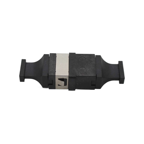
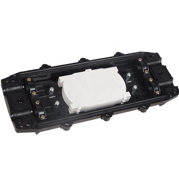
A fiber-optic cable, also known as an optical-fiber cable, is an assembly similar to an electrical cable but containing one or more optical fibers that are used to carry light. The optical fiber elements are typically individually coated with plastic layers and contained in a protective tube suitable for the environment where the cable is used. Different types of cable are used for fiber-optic communication in differen. DesignOptical fiber consists of a and a layer, selected for due to the difference in the between the two. In practical fibers, the cladding is usually coated wit. In September 2012, NTT Japan demonstrated a single fiber cable that was able to transfer 1 per second (10 bits/s) over a distance of 50 kilometers. Although larger cables are available, the highest stra. This list includes both standards-based and real-world technical cable types utilized in fiber-optic infrastructure, telecoms, enterprise, and outdoor applications. • OFC: Optical fiber, conductive• OFN: Optical fibe.
[PDF Version]
In the last twenty years, optical networks have witnessed recurrent changes in their management and control architecture. In this paper, we present a historical timeline and a future perspective of the evolution.
The formula is simple: sum the cross-sectional areas of all cables inside the conduit, divide by the conduit's inner area, multiply by 100. Use this calculator to estimate total optical attenuation across your network and confirm system performance against recommended design margins. The tool accounts for fiber attenuation, connector and splice losses, splitters, and other passive components, helping ensure reliable transmission in. A tool that computes how many fibers fit in a circular bundle and splits them into user-defined segments for cable-assembly planning. Key Parameters: • Center Diameter, Fiber Diameter, Packing Efficiency, Section Count Calculation: Visualization: • Color-coded radial diagram with per-section. Fill ratio — sometimes called fill percentage — is the ratio of the total cross-sectional area occupied by cables to the interior cross-sectional area of the conduit, expressed as a percentage.
[PDF Version]
Snell's Law is especially important for optical devices, such as fiber optics. Snell's Law states that the ratio of the sine of the angles of incidence and transmission is equal to the ratio of the refractive index of the materials at the interface. The values presented below are approximate and should be considered as such, as standardized values are still evolving. The image above illustrates the power loss per kilometer for various. A fiber optic connector is a mechanical device that allows two fibers to be joined precisely, enabling light to pass with minimal insertion loss and reflection. A good connector: Provides low insertion loss (minimal signal attenuation). Most people are familiar with Snell's. Ciena is the global leader in high-speed connectivity. Learn how GeoMesh Extreme unifies submarine, terrestrial, and cloud networks. Unprecedented capacity, latency, and. The fiber loss in the S-band (Short-wavelength Band) (short-wavelength band: 1460-1530 nm) is lower than that in the O-band, and the S-band is used as many PON (passive optical network) systems.
[PDF Version]Contact us for competitive quotes on any of our power communication and smart grid products
Get a Quote