
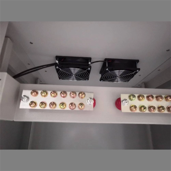
Learn the correct sequence: LV off before HV, control before main, and never operate isolators under load. Power Off and Power On Sequence in the Distribution Room When de-energizing, first disconnect the low-voltage (LV) side, then the high-voltage (HV) side. First open all LV branch circuit breakers, then open the LV main breaker. When an overload or short circuit occurs, the breaker rapidly interrupts the flow of electricity, preventing conductors from overheating and potentially starting a. Phase 3's Powersafe Sequential Mating Box controls the connection sequence of incoming / outgoing high current cable connections. With key (included) turn the Earth lock clockwise. These switches are responsible for protecting the electrical circuits from overloads and short circuits. By referring to the wiring diagram, you can easily identify which circuit. Connection method: Each switch takes a wire from the incoming point and connects it to the incoming end of the switch, or uses parallel connection to reduce the difficulty of wiring.
[PDF Version]
In electric power distribution, a busbar (also bus bar) is a metallic strip or bar, typically housed inside switchgear, panel boards, and busway enclosures for local high current power distribution, transmission, or switching substations. They are also used to connect high voltage equipment at electrical switchyards, and low-voltage equipment in battery banks. They are generally uninsulated, and h. Design and placementThe busbar's material composition and cross-sectional size determine the maximum current it can safely carry. Busbars can have a cross-sectional area of as little as 10 square millimetres (0.016 sq in), but. • – Data transfer channel connecting parts of a computer• – Low resistance electrical conductor for high current transmission and distribution• – Modular approach t. • Elmore, Walter A. (1994). Protective Relaying Theory and Applications. Marcel Dekker.• Paschal, John (2000-10-01). Electrical Construction & Maintenanc.
[PDF Version]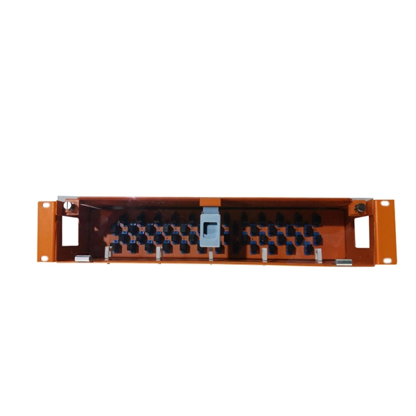
What is an Optical Switch Module? An optical switch module is an optical device featuring one or more selectable transmission ports, designed to physically switch or logically manipulate optical signals within an optical transmission line or an integrated optical circuit. Thorlabs' offers a selection of optical switches. Also available are. Optical switching is the process of controlling the destination of individual optical information signals. Figure: Optical Switch. POLATIS ® Series 6000 Optical Switch Modules (OSM) are high-performance, fully non-blocking all-optical matrix switch modules with port counts from 16xCC up to 48xCC, offering "any-to-any" port connectivity. 2 dB), fastest switching speed (10 ns), broadest wavelength range (300–2400 nm), widest fiber compatibility, highest optical power handling (50 W), and space-qualified reliability.
This article explains how to power up more PoE devices (PDs), what's the difference between 802. 3at mode as well as the difference between classification and consumption mode in Power over ethernet on your switch . PoE: Power over Ethernet (PoE) is a technology that allows Ethernet cables to carry electrical power, along with data, to powered devices. The initial allocation for Class 0, Class 3, and Class 4 powered devices is 15. This allows a single cable to provide both a data connection and enough electricity to power networked devices such as wireless access points. When working with your network devices, it's important to understand each device's power requirements and the types of Power over Ethernet (PoE) they support. Power is passed from Power Sourcing Equipment (PSE) over the twisted pairs to Powered Devices (PD) such as IP phones, IP cameras, card.
the redundant operation of aggregation/distribution switches, increases the reliability of the aggregation layer, and connecting the relevant access switches to two different network nodes in the aggregation/distribution layer ensures an extremely. Stacking, i. in 3 switches, one acts as Master - it has all config Layer 2 and Layer3 (rest 2 switch act as a member do not hold any config) Once the master switch failed next slave switch becomes master electing stat functioning as expected. you can. The S5860-20SQ 24-port 10Gb Ethernet layer 3 switch features 20x 1G/10G downlinks, 4x 10G/25G SFP28 and 2x 40G QSFP+ (can be split into 4x 10G SFP+) uplinks that all support virtual stacking. This managed enterprise switch adopts cutting-edge Broadcom chips to deliver 760 Gbps switching capacity. Switch stacking is a method of binding multiple switches so that they can act as a single switch. This method is applicable on access layer switches. They require a strategy to prevent this sort of disruption from occurring again. Any suggestions? Perhaps break it up into. Stacking, i.
[PDF Version]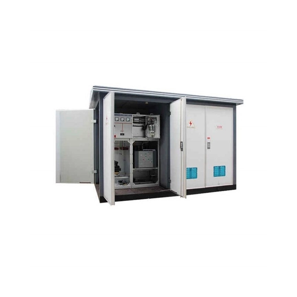
The hot wire (usually black) carries live current from your breaker panel. Green or bare copper ground wires provide emergency pathways for stray voltage. Cable trays: Cable rails are flat structures that can hold several cables at the same time. EMC stands for Electromagnetic Compatibility. However, the idea is always the same - electrical devices are not allowed to interfere with each other. The purpose of this presentation is to introduce some practical methods. Signal cables or weak-current cables inside cabinets are sorted by cable managers, cable rings, and cable trays. Power enters through connectors like WAGO 221 lever nuts, splitting into two directions. "Proper conductor. Certain preconditions in the Engineering Base project must be fulfilled to get an errorless routing when using the assistant Cabinet Routing. After the successful execution of the Cabinet Routing the worksheet “Routing Infor-mation” is displayed which contains information about the routed wires.
[PDF Version]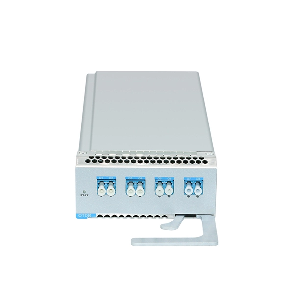
Strain relief bar (SRB) is a cable management solution, which in most cases, attaches to the back of the rails via the strain relief bar brackets. It also helps you arrange interface cables in such a way that the power modules, fan assembly, and air filte n for the Cisco 10005 router. The cable management bracket enables you to route the cables outside the router and away from the Routing Engines and LMICs. Figure. These rack types are broken down in Table 2 into 4-post and 2-post styles. 4-post rack types contain vertical mounting flanges with either square-hole, unthreaded round-hole, or threaded round-hole designs as part of the rack and rail interface. This washer is not installed. The following guidelines provide cabling information for installing, migrating, relocating, or upgrading your system: Position drawers in racks to allow enough space, where possible, for cable routing on the bottom and top of the rack, and between drawers. Shorter drawers must not be placed between.
[PDF Version]
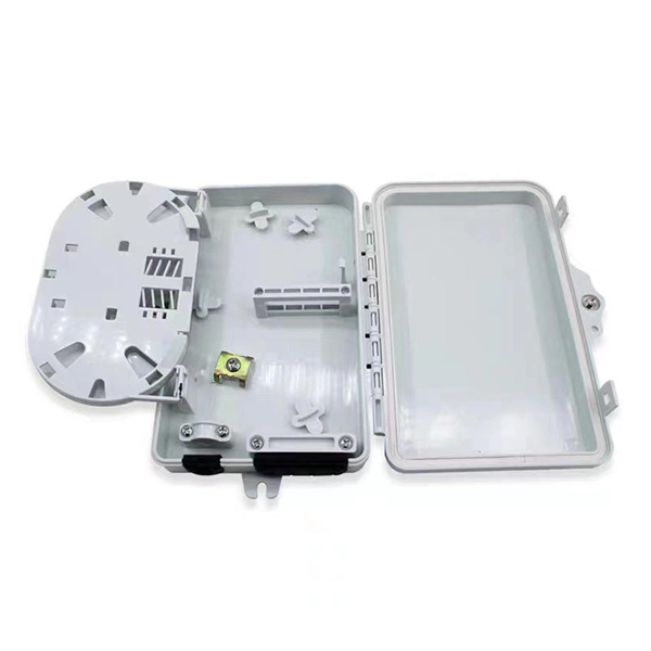
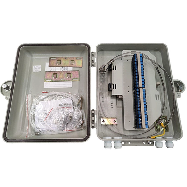
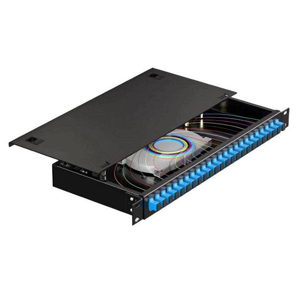
Begin by routing each fibre patch cable through the designated cable pathways. Use structured systems like cable trays, ducting, or raceways to prevent clutter and protect fibres from damage. Correct patch-cord installation is essential for maintaining low insertion loss, stable return loss, and long-term reliability in both indoor and outdoor fiber networks. Proper handling, routing, cleaning, bend-radius management, and connector alignment ensure that the optical link meets design. Incorrect routing, contamination, or physical stress on a fiber optic cable can result in attenuation, signal loss, and even complete link failure. According to data from NS Comm's Fiber Performance Lab (2024 Q4 Test Report), poor installation practices can cause up to 2. 5 dB additional signal loss. Proper cable routing, clean connector mating, and adherence to bend radius guidelines aren't optional—they're essential for sustaining long-term network performance and infrastructure lifespan. Ground Outlet: Cables enter inside the rack from the bottom, meaning the patch panel should be mounted in the lower part inside the rack.
[PDF Version]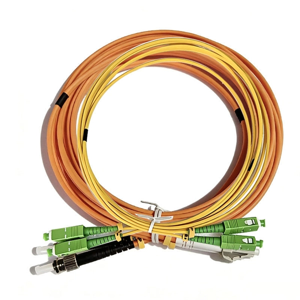
Over voltage protection relays detect when the current's voltage exceeds a preset value. The entire system will shut down. It prevents safety hazards and damage to equipment. Many industries use voltage protection relay systems, especially those in high-voltage. Relays designed for voltage protection are fundamental in today's electrical systems as they help in mitigating equipment damages and also prevent infrastructural breakdowns arising from voltage anomalies. It continuously measures voltage levels within electrical systems, and if it recognises a voltage problem that might. Protective Relay Definition: A protective relay is an automatic device that senses abnormal conditions in electrical circuits and triggers actions to isolate faults. It works by monitoring incoming power and disconnecting the circuit if the voltage becomes too high or too low.
These aggregation switches typically operate at Layer 2 or Layer 3 of the OSI model, depending on the network topology and configuration requirements. The three layers of a traditional three-layer network design are the core layer, aggregation layer, and access layer. By design, it therefore provides resiliency because it will always be deployed in pairs of switches and comes with a recommendation to deploy only dual hot swappable power supplies and redundant fans in each switch to. Switch aggregation refers to the concept of consolidating multiple access layer switches into a single aggregation layer switch in a traditional three-tier network design. Moderate Performance: Choose moderate performance switches that can handle traffic from multiple access layer switches. Redundancy and High Availability: Deploy.
Contact us for competitive quotes on any of our power communication and smart grid products
Get a Quote