

Remove the CPU module from the relay housing and set aside. Be certain to align the printed circuit board with the card guides in the housing. Always use antistatic bags for transporting modules Remove AC power and DC power from the PCD before removing, installing or wiring any of the PCD modules. Consult. What are the steps for safely removing and reinstalling a PLC CPU module? Safe removal and reinstallation of a PLC CPU module requires strict adherence to proper procedures to prevent equipment damage, data loss, or safety hazards. Consult the most recent PCD Instruction Book for details on programming the new CPU to suit your requirements. 0 or Modbus ASCII communications, protocol documentation is available. 1. 1 INTRODUCTION TO THE UR The GE Universal Relay (UR) series is a new generation of digital, modular, and multifunction equipment that is easily incorporated into automation systems, at both the station and enterprise levels. In particu-lar, one will find: General information with regard to design, configuration, and operation of SIPROTEC 4 devices are set out in the SIPROTEC 4 System Description /1/.
[PDF Version]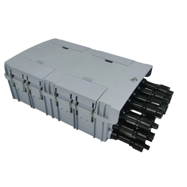
It covers zero voltage verification (ZVV) when a lockout is being performed; it must be followed in all cases in which an electrical hazard exists and the equipment or system must be de-energized and locked out before work is performed. of NFPA 70E, Standard for Electrical Safety in the Workplace, there is a specific and approved approach to establishing an electrically. The testing and verification of relay protection devices can be divided into four groups: Type tests are needed to prove that a protection relay meets the claimed specification and follows all relevant standards. Consult Quality or Product Engineering for advice. What is an Over Voltage Relay? What is an Undervoltage Relay? When the voltage and time values cross, a tripping signal is sent to circuit breaker. Purpose: To document and implement programs for the maintenance of all Protection Systems, Automatic Reclosing, and Sudden Pressure Relaying affecting the reliability of the Bulk Electric System (BES) so that they are kept in working order. This standard establishes a common reproducible basis for designing and evaluating relays and relay systems.
[PDF Version]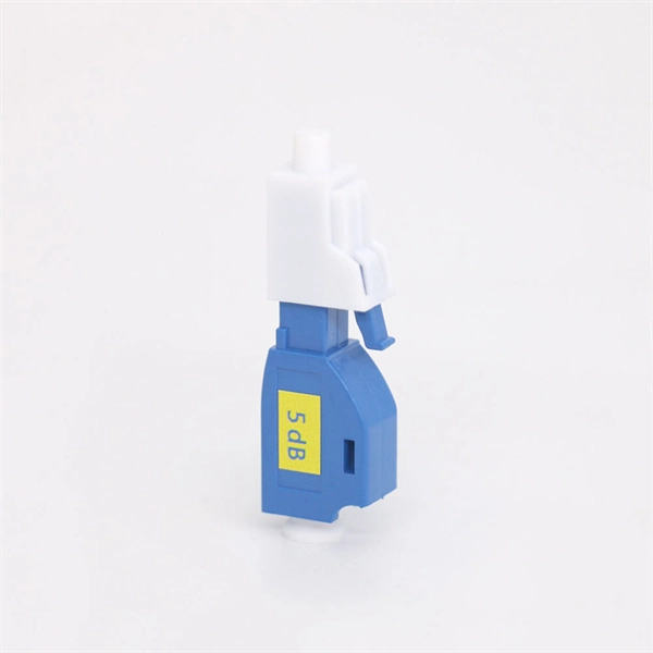
With the emergence of AC/DC hybrid power grids and the large-scale incorporation of new energy to the power grid, modern power systems have put forward more requirements for relay protection. With the powerful processing capability of microcomputers, relay. able sources such as wind and solar. Nowhere is that clearer than in the challenge to. Protective relays and devices have been developed over 100 years ago to provide “last line” of defense for the electrical systems. These devices detect abnormal conditions within electrical grids, including faults and overloads, and trigger corrective measures to prevent. What it is: Think of relay coordination as the “brain” of the power grid—it's the art of making sure that when a fault happens (like a tree falling on a wire), only the local area loses power while the rest of the city stays bright. The Goal: We use 7 core principles to protect people, save. The main protection must operate normally even when one transmission line is not in use.
[PDF Version]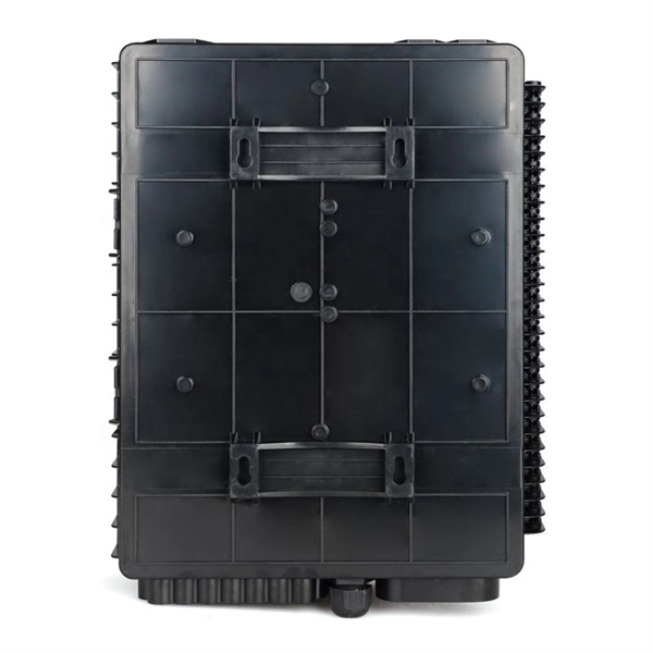
100 describes characteristics, construction, test methods, and performance criteria of optical fibre cables installed by pulling method for duct and tunnel application. Note that Recommendation ITU-T L. Electrical properties are specified for optical ground wire (OPGW) and optical phase conductor (OPPC) cables. 0, in February. This standard BS EN IEC 60794-1-209:2024 Optical fibre cables is classified in these ICS categories: IEC 60794-1-209:2024 defines test procedures to be used in establishing uniform requirements for the environmental performance of: - optical fibre cables for use with telecommunication equipment and. The International Electrotechnical Commission (IEC) is the leading global organization that prepares and publishes International Standards for all electrical, electronic and related technologies. The technical content of IEC publications is kept under constant review by the IEC.
[PDF Version]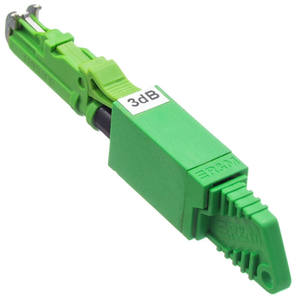
Our relay protection tester offers comprehensive testing for both optical digital and traditional protective devices. It's ideal for power plants, substations, equipment manufacturers, and institutions needing relay protection evaluations. Versatile Outputs: Supports up to 6-phase voltage/current. Compact relay test set for quick and easy manual three-phase testing Ultra-portable test set for primary and secondary injection, as well as basic protection tests Modular, multi-phase protection relay test set and commissioning tool Compact relay test set for quick and easy manual three-phase. Power System protection is crucial part of power station and substations safety which use protection relays and circuit breakers to isolate faulty parts or zones within the plant including Generator zone, Motor zone, Feeder zone, Bus zone, Transformer zone and Transmission Lines zone. Hence a. Protection relay tester which offers all the characteristics and functions needed for protective relay testing, in a manual or automatic mode, designed for maximum efficiency, flexibility and simplicity, with the required accuracy and performance to test any kind and type of relays in all.
[PDF Version]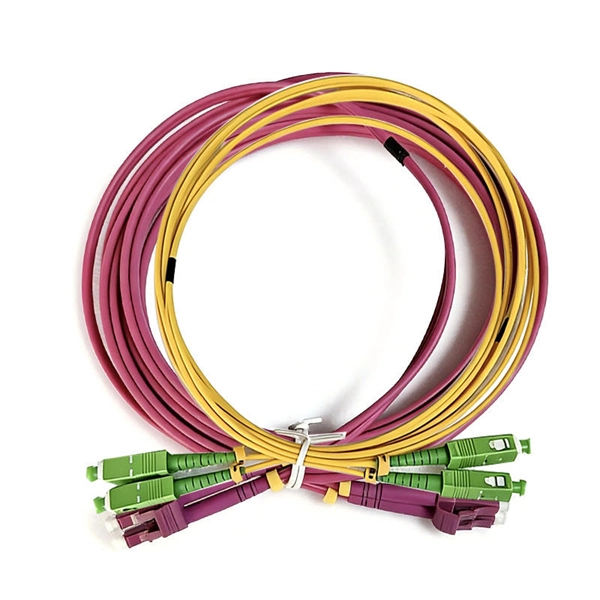
This is a lab setup for the practical demonstration of wiring a distribution board with several loads - lights, geyser, and plugs. Loads protected by earth leakage with over current circuit breaker protection. Further details found in the SANS 10142-1:2020 wiring standard - The Wiring of Premises. Fixed setting RCD with a rated operating residual current not exceeding 30mA. RCDs with a sensitivity of 30mA is. Three phase RCCB is used in domestic and industries. Earth Leakage fault occurs due to improper connection, insulation failure, moisturization in electrical circuits, human. The specific wiring methods may vary slightly depending on the type of leakage protector and the application scenario. The following takes the common household single - phase leakage protector and three - phase four - wire leakage protector as examples to introduce their basic wiring methods: -. In this Video you will learn how a DB is wired, I cover Circuits Breakers, Earth Leakage, Earth and Neutral Bars, and more. In this video you will learn.
[PDF Version]
Testing a splitter or other passive fiber optic devices like switches is little different from testing a patchcord or cable plant using the two industry standard tests, OFSTP-14 for double-ended loss (connectors on both ends) or FOTP-171 for single-ended testing. First we should define what these. Splitter loss refers to the reduction in optical power that occurs when a single optical signal is divided among multiple output ports in a fiber optic network. Insertion loss testing of the optical splitter is very important to ensure compliance to the optical parameters of the manufactured. Optical splitters are vital components in fiber optic networks, distributing signals from a single input fiber to multiple output fibers. Here is a table of typical losses for splitters. Signal loss within a system is expressed using the decibel. The CertiFiber® Pro Optical Loss Test Set (OLTS) can be used to check that the loss of a PON Splitter (often referred to in various standards as a non-wavelength-selective or wavelength-selective branching device) to check that it is within the allowed defined limits. The CertiFiber® Pro has an.
[PDF Version]Contact us for competitive quotes on any of our power communication and smart grid products
Get a Quote