
Signal-to-Noise Ratio (SNR) represents the power ratio between the desired signal and background noise, affecting the clarity of the received signal. Higher SNR values generally lead to lower BER, as stronger signals reduce the probability of error during data decoding. A high OSNR indicates a low level of noise in the system, which is critical for. The Signal-to-Noise Ratio (SNR) is a crucial metric that helps us understand the quality of signals in a system. It is defined as the ratio of the number of bits received in error to the total number of bits transmitted.
In, the number of bit errors is the number of received of a over a that have been altered due to,, or errors. The bit error rate (BER) is the number of bit errors per unit time. The bit error ratio (also BER) is the number of bit errors divided by the total number of transferred bits during a studied time interval. Bit er.
Researchers in the past have analyzed the detrimental effects of the dispersion in optical channels. However, efficient techniques of management of dispersion effects are limited, as huge data is aggregated, w.
In digital transmission, the number of bit errors is the number of received bits of a data stream over a communication channel that have been altered due to noise, interference, distortion or bit synchronization errors. The bit error rate (BER) is the number of bit errors per unit time. The bit error ratio (also BER) is the number of bit errors divided by the total number of transferred bits during a studied tim. ExampleAs an example, assume this transmitted bit sequence: 1 1 0 0 0 1 0 1 1 and the following. The packet error ratio (PER) is the number of incorrectly received divided by the total number of received packets. A packet is declared incorrect if at least one bit is erroneous. The expectation value of the PER is. In a communication system, the receiver side BER may be affected by transmission channel,,, problems,, wireless , etc. The BER m.

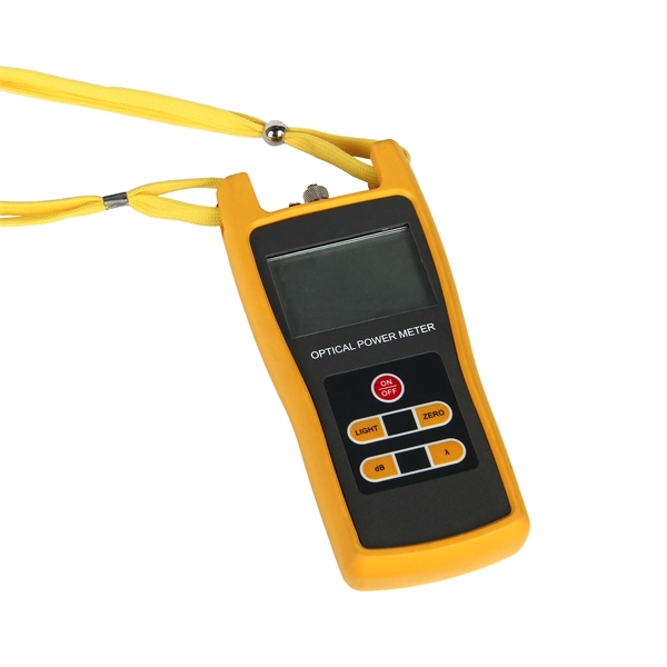
Bit Error Ratio Tester is an instrument used to test and analyze bit error ratio in digital transmission systems, fiber optic communication systems, and digital microwave communication systems. The MATRIQ BERT 1001/1005 series instruments are dual-channel or four-channel PPGs and error detectors for the development, characterization, and production of optical transceivers. Whether you are looking for the smallest handheld 100G bit error rate tester in the world for your field job, or perhaps your needs take you into the lab, VIAVI has you covered with our accurate and easy-to-use BERT equipment for any use case. The T-BERD/MTS-5800-100G handheld network tester is the. Applications for OPTELLENT's products include testing of ICs, optical components, modules (transceivers) and subsystems, networking equipment, and network installation and maintenance. OPTELLENT specializes in offering customized features on its products with short lead times. Offers precise, cost-efficient optoelectronic signal and anomaly testing for high-speed transceivers. By simulating data transmission and.
[PDF Version]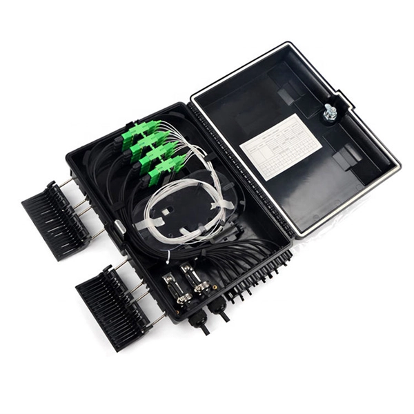
In 4G network, the optical modules used to connect BBU and RRU are mainly Gigabit to 10 Gigabit optical modules; in 5G network, the optical modules used to connect BBU and RRU are mainly 25G rate. RRU is short for remote radio unit. It also provides information about the RRU and its cables. The actual exteriors may be different. Product Versions The following table lists the product versions related to this. Can use 3. 5G rate optical module to complete the multiplexing of low-speed interface services such as 4G at a lower cost; Also used for 40KM long-distance transmission of 10G rate interface (10, 20KM for 1271nm~1371nm window). 25G SFP optical module adopts the wavelength of 850nm, with an operating. The Gamma632 is a 4G&5G dual-mode Remote Radio Unit (RRU) product independently developed by Baicells with independent intellectual property rights.
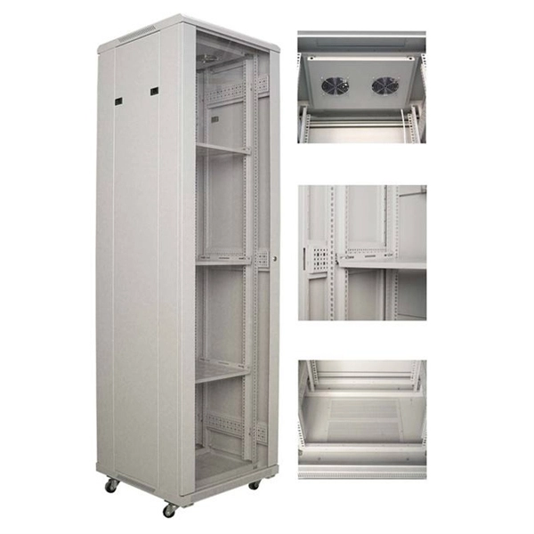
Enterprise SONiC based 32 port 100G QSFP28 aggregation core switch for aggregation spine architecture, which line rate L2 L3 up to 3. 2Tbps, Marvell Falcon, ROCEv2 EVPN Multi homing supported. FS 100G Switches offer high programmability and scalability, designed for large enterprises and hyper-converged infrastructure (HCI) networks. Learn more!d data centers and carrier access providers. The AGR100 provides switching at Layer 2 or Layer 3 ac oss 48 x 10 GbE ports and 6 x 100 G uplinks. The switch can be deployed either as a Top-of-Rack switch, as part of a 100 GbE or 40 GbE distributed spine, forming a non-blocking folded-Clos data. In data-intensive, distributed campus networks, the LANCOM YS-7154CF ensures the necessary performance and high availability of network resources. 6. The product has completed the End of Life (EOL) process effective on January 1, 2026. Cisco ® ASR 9900 12-port 100 Gigabit Ethernet line cards deliver industry-leading high density and line-rate 100 Gigabit Ethernet ports to any slot of a Cisco ASR 9900 Series Aggregation Services Router.
[PDF Version]
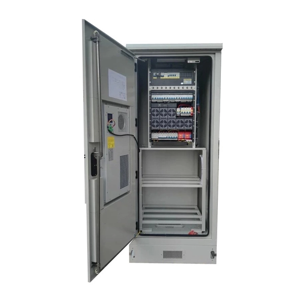
What Is a Distribution Box?A distribution box, also known as a power distribution unit, is a critical component in any electrical system. It is the control center fo.
Troubleshooting common issues in Industrial Ethernet networks involves identifying and resolving problems like connectivity failures, slow communication, or data loss. Industrial switches play a critical role in complex industrial environments, but their hardware failures are often influenced by multiple factors such as power supply, indoor temperature, humidity, electromagnetic interference, and static electricity. When a switch fails in a control system network, PLCs lose communication with HMIs, SCADA masters lose contact. This guide walks through the most common causes of industrial automation communication failures, how to diagnose them efficiently, and which components are most often involved—so you can restore control without unnecessary part swapping or guesswork. Start by checking the physical connections, including cables, connectors, and switches.
Contact us for competitive quotes on any of our power communication and smart grid products
Get a Quote