
These distances are influenced by voltage level, pollution degree, and the system insulation category. The IEC 61439-1 standard is the most commonly used document for defining these values., PVC dipping, epoxy. In busbar clearances and creepage distances, the first distinction is simple but critical. It applies to low-voltage switchgear and control gear assemblies and provides a table of minimum clearances. This article provides a brief explanation of their significance and the possible faults that may arise if these. Ensuring clearances and creepage distances meet the minimum requested by the standard avoids problems for nominal voltage and overvoltage such as: Before we get into how you can meet these requirements, let's define terms: What are clearances and creepage distances in LV switchboards? What are the. Clearance - the distance between two conductive parts along a string stretched the shortest way between these conductive parts.
[PDF Version]
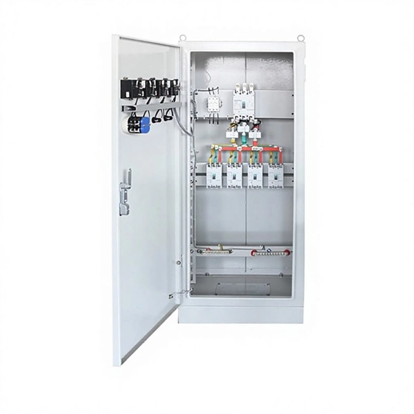
The horizontal distance between switchbox and fixed electrical equipment should not exceed 3m. 26, these rules define the minimum Spaces about electrical equipment necessary for. The IEC (International Electrotechnical Commission) and BS 7671 (British Standard for Electrical Installations) both provide essential requirements for electrical installations, including those for fuse boards like garage unit, consumer unit and distribution board. While the IEC 60364 standard. These requirements vary depending on whether the electrical equipment is rated at (1) 1,000 volts or less (See, Article #2) or (2) over 1,000 volts.
The IEC has published a new standard for the testing of fibre optic cabling. IEC 61280-4-5 provides test methods to measure the attenuation of installed multimode and single-mode optical fibre cabling plant as well as the determination of their polarity and length. Fiber optic testing of a newly installed system not only verifies that the system meets its design requirements, but also creates a performance baseline for all future testing and troubleshooting of t at system. Corning recommends that all fiber optic systems be tested to a minimum set. for installing electrical products and systems. NEIS® are intended to be referenced in contrac documents for electrical construction ation or liability to users of this publication. Lower attenuation means less signal loss over distance. Patch cords and jumper cables must meet stricter performance requirements because connectors. ANSI/TIA‑568.
[PDF Version]
Specifications must be strictly followed in the installation process: the height deviation of the support points in the horizontal section is ≤3mm, and the deflection of the vertical section is ≤2mm/m; the connecting bolts are made of grade 8. 8 galvanized parts, and the M10. The most common type of copper used. With a minimum copper content of 99. 90%, and an electrical conductivity of 101% IACS, it is used in such diverse applications as electrical conductors, roofing and flashing, heat exchanger fins and tanks. The IEC 61439. According to the different material states, copper busbars are divided into hard copper busbars (TMY) and soft copper busbars (TMR). The hard products are cold work hardened and the Vickers hardness is controlled at 80-120HV. Rated Current: The Logical Starting Point for Selection Accurately calculating the rated current is the. WILLELE provides high-quality copper comb busbars and DIN rails for reliable circuit connection and modular panel assembly.
[PDF Version]
Spacing Standards: Electrical (power) and instrumentation (signal/control) cable trays should maintain a minimum vertical and horizontal distance. Dividers or Partitions: Where. Support spacing for cable trays must align with the manufacturer's instructions, as outlined in NEC 392. Generally, standard trays require supports every 6 to 10 feet, while heavy-duty, long-span trays can handle distances of up to 20 feet between supports. In planning a project, one has a choice of either utilizing numerous. National Electrical Code (NEC) specifies the capacities of cables rated at 2000 volts or less in cable trays. NEC governs pathway compatibility; TIA governs spacing to mitigate EMI and mechanical interference. Best Practice: Unshielded data cable vs. power cable requires 12 inches of separation unless a listed barrier or separate.
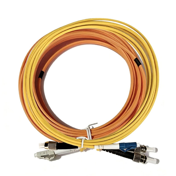
Fiber optic cable can be run anywhere from 300 meters up to 80 kilometers (roughly 50 miles) depending on the cable type, transceiver used, and network standard. Such fibers are widely used in fiber-optic communication, where they permit transmission over longer distances and at higher bandwidths (data transfer rates) than. Many factors decide the fiber cable distance, but the key factors include the below six aspects. Attenuation First is the attenuation of the optical fiber. The greater the distance, the greater. With ideal conditions and amplification, optical fiber can transmit petabit speeds globally, but real-world limits depend on fiber type and network design.
The normal recommendation for fiber optic cable is the minimum bend radius under tension during pulling is 20 times the diameter of the cable (d). Burst pressure ratings for pigtails are determined at room temperature with the hose in a straight line. A safety factor of 4:1 or 5:1 should be used for normal applications. The connectors work in a frequency range of up to 6 GHz and guarantee maximum component density thanks to their low overall height of 2. 5mm and a space requirement of just 3mm². We offer over 6,000 different Types and Sizes of RoHS Compliant Liquid Tight Strain Relief Fittings, Cord Grips, Cable Glands, Circular Connectors, Conduit System, Industrial Enclosures and Other Related Cable Management Products which are rated the best in the industry. From Table 3, the formula is “F x OD” and, from.
Contact us for competitive quotes on any of our power communication and smart grid products
Get a Quote