

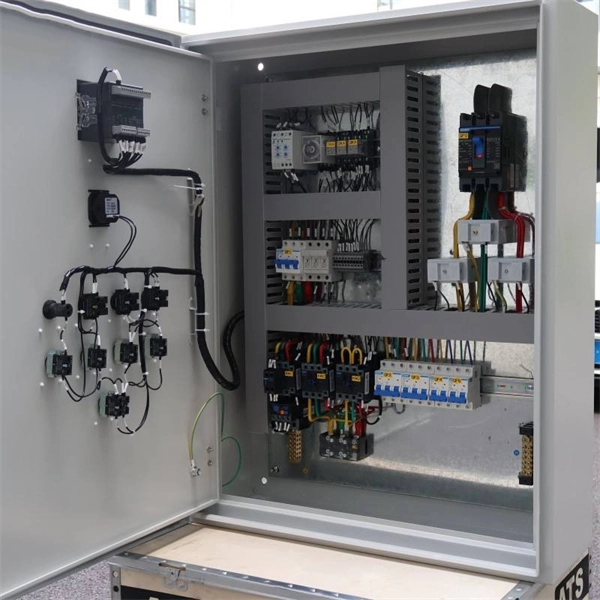
Remove the CPU module from the relay housing and set aside. Be certain to align the printed circuit board with the card guides in the housing. Always use antistatic bags for transporting modules Remove AC power and DC power from the PCD before removing, installing or wiring any of the PCD modules. Consult. What are the steps for safely removing and reinstalling a PLC CPU module? Safe removal and reinstallation of a PLC CPU module requires strict adherence to proper procedures to prevent equipment damage, data loss, or safety hazards. Consult the most recent PCD Instruction Book for details on programming the new CPU to suit your requirements. 0 or Modbus ASCII communications, protocol documentation is available. 1. 1 INTRODUCTION TO THE UR The GE Universal Relay (UR) series is a new generation of digital, modular, and multifunction equipment that is easily incorporated into automation systems, at both the station and enterprise levels. In particu-lar, one will find: General information with regard to design, configuration, and operation of SIPROTEC 4 devices are set out in the SIPROTEC 4 System Description /1/.
[PDF Version]
ALCAN Systems is developing a new class of innovative smart antennas—ultra thin flat panel technology, very low power usage, and able to adjust its beam electronically without any moving parts—at an extremely affordable price. While the industry-standard OSFP (Octal Small Form-Factor Pluggable) module has successfully enabled 400Gbps, 800Gbps, and 1. 8Tbps of switching. 6Wresearch actively monitors the Afghanistan Coherent Optical Equipment Market and publishes its comprehensive annual report, highlighting emerging trends, growth drivers, revenue analysis, and forecast outlook. Our insights help businesses to make data-backed strategic decisions with ongoing. Optogonstudio is a leading provider of optical designs for wearable devices and health applications. With a focus on optical module design, sensor design, and component manufacturing, we excel in optical sensing, metrology, and micro-optics. We are dedicated to helping you build, connect, protect and optimize your network. The result is a high-performance, future-proof data connectivity.
[PDF Version]
Discover the HJDUM03 Series Embedded Communication Switching Power Supply System, designed for communication applications. Features include wide AC input voltage (90Vac ~ 300Vac), 96% conversion efficiency, intelligent battery management, RS485/TCP/IP monitoring, and. Huijue Group's energy storage solutions (30 kWh to 30 MWh) cover cost management, backup power, and microgrids. To cope with the problem of no or difficult grid access for base stations, and in line with the policy trend of energy saving and emission reduction, Huijue Group has launched an. Founded in 2002, Huijue Group is a high-tech service provider integrating intelligent energy storage equipment and computer intelligent network communication system integration and application. Huijue Network's products are exported to Europe, North America, Southeast Asia and other countries and. View results and find huijue 4 series core switch datasheets and circuit and application notes in pdf format.
[PDF Version]
Serial to Fiber converters transform serial communication signals into optical signals transmitted over fiber optic cables, enabling long-distance, interference-free data transmission in industrial networks. As industries increasingly rely on long-distance data communication, serial to fiber converters have become essential, effectively connecting. Moxa's industrial-grade serial-to-fiber optic converters can convert RS-232/422/485 to optical fiber, which provides users with an easy and reliable way to communicate with their serial devices. A verification email has been sent to {0}. Please click on the link in this email to verify your address. DYMEC is renowned in the power utility and switchgear industries for decades of reliable service with our DYMEC 5844 line.
FEC encodes outgoing data with additional bits based on well-defined mathematical rules. The receiver uses these bits to detect and correct a limited number of errors caused by impairments like dispersion, noise, or crosstalk. Block-based codes widely used in Ethernet and. By embedding redundant data that allows receivers to correct errors without retransmission, FEC delivers high-speed performance with low error rates, ensuring both scalability and cost-effectiveness. The addition contains sufficient information on the actual data to enable the FEC decoder at the receiver end to. O-FEC is an advanced forward error correction algorithm based on block turbo codes with soft-decision iterative decoding. Originally developed for the Open ROADM specifications and later adopted by the OpenZR+ Multi-Source Agreement (MSA), O-FEC provides approximately 11 to 11. That's why FEC is vital in situations where delays just aren't an option, like live video streaming, satellite links, or real-time voice calls.
[PDF Version]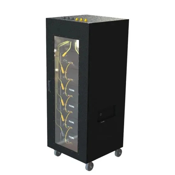
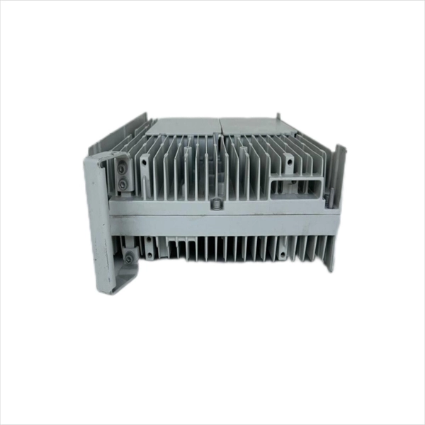
Optical module usually consists of a transmitter assembly (TOSA, containing a laser LD chip), a receiver assembly (ROSA, containing a photodetector PD chip), a driver circuit, an optoelectronic interface, a heat sink (some models), a housing, a pull ring and so on. Integrated circuits and reference designs help you create a smaller and faster optical module design used in high-bandwidth data communication applications. Whether you are creating a 100-Gbps or 400-Gbps, small form-factor pluggable (SFP) module, SFP+ transceiver, XFP module, CFP, X2/XENPAK module. Structure 5. Overview The optics module is comprised of Si photodiodes, optical components, and current-to-voltage conversion circuit. Its primary function entails converting electrical signals into optical signals. This assembly comprises a light source, such as a laser diode or a semiconductor light-emitting diode (LED), an optical interface, a. Average optical power refers to the optical power outputted by the optical module's transmitter under normal working conditions, which can be understood as the intensity of light.
[PDF Version]
Operating at the physical layer of the OSI model, optical modules are core devices in optical fiber communication systems. Just as data centers begin their transition to 400G and 800G, the bar is rising towards the next evolution of 1. 2T, with the same demands for high performance and low power with minimal financial impact. They are. As an essential component of optical fiber communication, optical modules are optoelectronic devices that facilitate the conversion between optical and electrical signals during the transmission process. With the goal of promoting worldwide compatibility of optical internetworking products, the OIF actively supports and extends the work of national and international standards. But the industry isn't stopping there— 800G modules are already in production, 1. 6 terabits per second) is on the cusp of commercialization, and 3.
The solution is to unplug the fiber and reinsert it into the SFP module interface until a “click” sound is heard, indicating the fiber connector and SFP module are properly connected. Contamination or damage on the fiber end face requires the use of a fiber end-face inspection. This guide will explore potential reasons and offer multiple fixed suggestions for those new to the transceiver world. SFP optical module failure usually occurs in two ways, the transmitting end and the receiving end. And the most common problems are mainly concentrated in the following aspects:. Have you ever experienced an unexpected network outage due to the failure of an SFP/SFP+ optical transceiver? Network outages can bring your ability to communicate and work to a halt, and your IT team will likely be frantically looking for a solution. Inspect the sfp module and cables. This article will help you troubleshoot a fiber optic module. Have you encountered challenges while utilizing transceivers within a network infrastructure? While clients can efficiently address common issues.
[PDF Version]Contact us for competitive quotes on any of our power communication and smart grid products
Get a Quote