
Scientists at the University of Southampton have developed a radical new hollow-core optical fiber that carries light through air instead of solid glass. The result? Data that moves faster, farther, and with a thousand times more transmission power than today's networks can handle. Hollow-core optical fibers (HCFs) have unique properties like low latency, negligible optical nonlinearity, wide low-loss spectrum, up to 2100 nm, the ability to carry high power, and potentially lower loss then solid-core single-mode fibers (SMFs). However, glass imposes a fundamental physical limitation because light travels through it approximately 30 percent slower than through air. Recent advances in reducing optical losses and the prospects for telecommunication applications of hollow-core fibers, issues of transporting high-intensity optical radiation, and results on nonlinear compression and the generation of ultrashort pulses in gas-filled hollow-core fibers are reviewed. This isn't just. In addition to beating conventional telecom fiber on loss and latency, hollow-core fibers are enabling new approaches to applications like sensing, fiber lasers and optical tweezers.
[PDF Version]
The bend radius of fiber cables is critical for maintaining high performance and longevity. During installation under tension, maintain a minimum bend radius of 20 times the cable's outer diameter, while post-installation requires a minimum long-term bend radius of 10 times the. Fiber optic cable bend radius is a critical mechanical parameter that determines how sharply a cable can be bent without risking microbending, macrobending, signal loss, or long-term structural fatigue. It is measured from the inside of the bend, not the outer curve. Installers must understand these specifications and know how to install cables without. Fiber optic cables are designed to withstand some bending, but excessive bends can physically damage the glass fiber or cause significant signal loss.
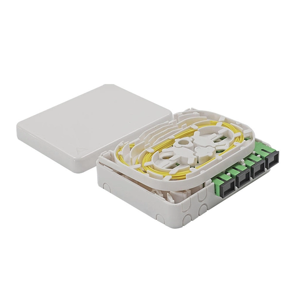
For optical fiber cables, each individual fiber is color-coded in a specific sequence to facilitate easy identification. The standard color sequence is based on a 12-fiber system, which repeats for cables with higher fiber counts. The TIA/EIA-598-C standard is the most widely followed guideline for color coding in optical fiber cables, both for loose-tube and. They each contain a central transparent core, usually circular in cross-section, surrounded by an annular cladding. The core can transmit light for long distances with low loss because of total internal reflection at the interface between. Prysmian uses the US industry standard repeating 12-color sequence. Tubes with binder threads: A blue and orange thread binder is used to separate two groups of fibers. The blue unit has the first 12 fibers and. Fiber Optics is the communications medium that works by sending optical signals down hair-thin strands of extremely pure glass or plastic fiber.
[PDF Version]
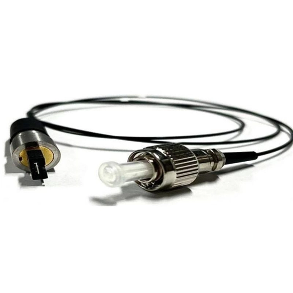
This paper describes a newly developed butt joint type hollow-core fiber connector with protected fiber ends. It can typically realize nearly 0.5-dB insertion and 45-dB return loss without physical contact. I.
This paper explains why it is not necessary to do so, based on the attenuation properties of optical fibers and the testing that is done by the fiber manufacturer. |OM2, OM3 and OM4 multimode fibers have traditionally been measured for attenuation at 850 and 1300 nm. The core diameter, cladding diameter and concentricity are the most important factors on how well one can connect or splice two fibers. However, LEDs are not coherent sources.

The ideal structure for connecting two fiber cables is as follows: Cable A → Adapter Panel → Patch Cord → Adapter Panel → Cable B How It Works Fiber Adapters: Bridge the two connector types (e., SC to LC, or SC to SC). Patch Cords: Provide a short, flexible link between adapters. To connect two optical fibers together, a process called splicing is used. This involves aligning the two fiber ends and then fusing them together using heat or a specialized tool. Fiber cabinets, patch panels, and distribution frames are designed to manage and protect terminations, not for direct splicing. Data Servers are at Location A.
In this lesson, we will identify and examine cables, then prepare them for splicing or termintion by stripping the cable to expose the coated fibers. It provides an expert-curated supplier directory, buyer-focused technical background information, and structured selection criteria to support professional procurement decisions. What are Fiber Strippers? Optical fibers are. In this video, we demonstrate the complete step-by-step process of fiber optic fusion splicing using the Fujikura 66S+ fusion splicer. What is Fiber Optic Splicing and Why is it Needed? – #1. Use and Maintain Your. Marcel Buijs, EMEA Business Development, Technical Sales, Fiber Optic Center, Inc. And tools used for fiber fusion: fusion splicer; fiber cleaver; cable stripper; fiber optic stripper; alcohol;.
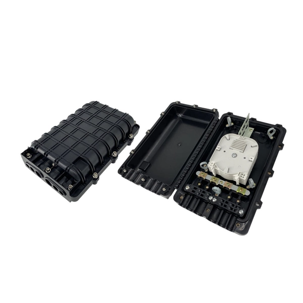
Optical Core Alignment (also called “Profile Alignment”), an optical alignment technique, is used by many models of fusion splicers. The two fibers are illuminated from two directions, 90 degrees apart. Fusion splicing is the process of fusing or welding two fibers together usually by an electric arc. The goal is to fuse the two fibers together in such a way that light passing through the fibers is not scattered or reflected back by the splice, and so that the splice and the region surrounding it are almost as strong as the. Fibre optic splicing trays are an essential part of manipulating and ordering optical fibers inside a network structure. Since the need for higher data rates and effective communication gets more robust, the utilization of optical fibers has become increasingly widespread across multiple spheres of. Corning splice trays use proven designs and fiber organization technology to provide optimum physical protection for fusion and mechanical splicing methods. The trays are engineered for use with indoor or outdoor splice hardware with both loose tube and tight-buffered optical cable designs.
[PDF Version]Contact us for competitive quotes on any of our power communication and smart grid products
Get a Quote