
Operating at the physical layer of the OSI model, optical modules are core devices in optical fiber communication systems. Just as data centers begin their transition to 400G and 800G, the bar is rising towards the next evolution of 1. 2T, with the same demands for high performance and low power with minimal financial impact. They are. As an essential component of optical fiber communication, optical modules are optoelectronic devices that facilitate the conversion between optical and electrical signals during the transmission process. With the goal of promoting worldwide compatibility of optical internetworking products, the OIF actively supports and extends the work of national and international standards. But the industry isn't stopping there— 800G modules are already in production, 1. 6 terabits per second) is on the cusp of commercialization, and 3.
Devices such as Optical Power Meters, OTDRs, and Visual Fault Locators help technicians measure signal loss, locate faults, and verify fiber integrity. Understanding how these tools work enables faster troubleshooting and more efficient fiber network maintenance. As the components like fiber, connectors, splices, LED or laser sources, detectors and receivers are being developed, testing confirms their performance specifications and helps. Fiber optic testing tools are essential for ensuring network reliability, performance, and proper installation. Our tools are indispensable for professionals requiring accurate fiber testing. The power meter is designed to accurately measure the optical power level of signals transmitted through the fiber optic cables, while the light source generates a stable and calibrated light signal that is transmitted through the fiber. Optical time domain reflectometer (OTDR) OTDR is an abbreviation for.
[PDF Version]
An Optical Power Meter and Laser Light Source will be used to measure power loss on each completed ring or distribution span to verify continuity between fibers (no fibers incorrectly spliced together). Fiber optic testing for continuity is crucial in ensuring that light transmits through fiber optic cables without interruptions, safeguarding seamless data transmission. Fiber optic. Fiber testers provide the precision needed to install, certify, and maintain high-speed optical networks. This category includes OLTS certifiers, OTDRs, optical power meters, light sources, and visual fault locators. For more information about FiberLert™ Live Fiber Detector, click here. Fiber QuickMap mainframe with SC/LC 50 µm Launch Fiber and carrying pouch. Our unique and innovate MPO Visual Cable Verifier Kit is versatile, inexpensive, and practical.
* The 10BASE-E channel shall have attenuation between 5 and 11 dB. If required an attenuator can be added to comply with this specification ** This is the maximum fiber attenuation allowed for standerd single mode fiber at 1550 nm as per IEC 60793-2. SFP-10G-LR Specifications: Optical, Electrical & Link Params provides a comprehensive, engineer-grade breakdown of the specification parameters that define the performance and interoperability of 10GBASE-LR SFP+ optical transceiver modules. These modules are widely used to deliver 10. 3125 Gbps. But on long haul single mode fibres I've always attenuated down 1 or 2 dbm to allow for fibre route changes on the provider network. It details the fiber's geometrical, optical. When testing fibre optic cabling, determining acceptable loss is crucial. This depends on various factors, including who is conducting the test and the phase of the project.
[PDF Version]
To investigate the optimal radial-arranged-position of the optical fiber in the cross-linked polyethylene (XLPE) power cable, the fibers were arranged into three positions, including segmental conductor c.
Fiber Optic Cable Testing Ensures network reliability by using tools like visible light sources, power meters, and OTDRs to measure signal loss, identify faults, and maintain system performance. Testing fiber optic components and cable plants requires making several measurements with the most common measurement parameters listed in the Table below. This note also provides background information on system link configurations, test equipment and system component considerations that influence. CERSA has developed a range of instruments using a variety of optical technologies to cover a wide range of applications and to meet production plant requirements for speed, precision, detection and characterization of fine defects. These measurements can then be displayed, recorded or analyzed. An OTDR helps pinpoint faults, breaks, and splices along a fiber link with serious accuracy. Crucial for certifying new links or troubleshooting existing ones.
[PDF Version]
The QSFP28 module provides 100GBase-LR4 throughput up to 10km over a standard pair of single-mode fiber (SMF) with duplex LC connectors. This transceiver is compliant with IEEE 802. 3ba 100GBASE-LR4, IEEE 802. 3bm, SFF-8665 and SFF-8636 standards. FS 100G Switches offer high programmability and scalability, designed for large enterprises and hyper-converged infrastructure (HCI) networks. The fiber optic ports are designed as SFP slots, therefore you can connect to any fiber type or different wavelengths by choosing a suitable SFP module. These advanced modules enable high-density, high-capacity connectivity, ensuring optimal performance. Fiber Mall 100G QSFP28 100GBASE-SR4 Optical Transceiver Module 850nm 100m MMF MTP/MPO D0M for Juniper Networks JNP-QSFP-100G-SR4 What is Desertcart? Is it safe to order from?+ The customer service exceeded my expectations. Perfect for buying products you can't find elsewhere.
[PDF Version]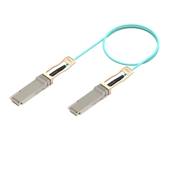
Single-mode fibers offer better bandwidth performance. However, they reach. There are two main types of fiber optic cables: single mode and multimode. Although they can do the same job in some instances, the different construction methods make each of them better suited to certain tasks and budgets. TOSLINK – Optical Audio. Optical fibers are among the most transformative technologies in modern photonics, quietly enabling the global internet, precision sensing, minimally invasive medicine, and high-power industrial laser systems.
A simple solution is to combine a Corning USB “A to receptacle-A” USB 3. Optical™ Cables by Corning with a short, off-the-shelf jumper cable that has a USB “A” plug on one side and the particular connector your end device requires on the other. 0 A female port of the AOC Cable. Vielen Dank für den Kauf dieses Optischen USB 3. Es unterstützt größere Distanzen als herkömmliche Kupferkabel, ist deutlich flexibler und leichter und daher optimal. A workaround would be to connect the USB 3. Once connected, check the Windows Device Manager to verify the devices that have been successfully connected through the device. The USB active optical cables are designed to be compliant with SuperSpeed USB and SuperSpeed+ USB electrical specifications, offering seamless interoperability between existing USB 3. 1 hosts, hubs and devices, ensuring a trouble-free plug-and-play experience. The USB AOC address the. Connect the USC-CC32 Type C device connector to the USB Hub.
[PDF Version]Contact us for competitive quotes on any of our power communication and smart grid products
Get a Quote