
Modern fiber optic networks usually keep splice loss low, as shown below: You should know that each splice can add 0. If losses add up, you may face poor signal quality and need more maintenance. This helps the network. Fiber optic pigtails are used to connect fiber optic cables using fusion or mechanical splicing. The estimate, called a "loss budget" is calculated using typical component losses for. Fiber splice loss measures how much signal drops when you join two fiber ends. The total loss in decibels at the fusion splice is given by the following equation, where Pin is the total power incident on the fusion splice and Ptrans is the. One problem I continue to see is unexpected high loss during spicing between exchange-to-exchange network, particularly in the feeder and backbone segments, which can seriously impact the performance of the PON networks. While drop fibers from the splitter to end users often receive less attention.
[PDF Version]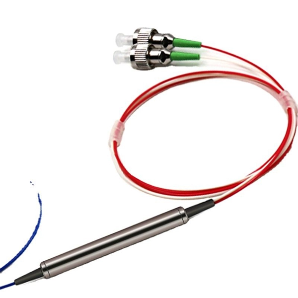
The Fiber Optic Cleaning Pen is a compact and effective tool for cleaning fiber optic connector end faces. Designed for SC, FC, ST (2. 25mm) connectors, it quickly removes dust, oil, and debris to ensure stable signal transmission and reduce connection loss. this cleaner efficiently removes. The electric fiber endface cleaning pen can completely remove anhydrous stains from the fiber endface and carry the stains away; Its high rotation speed achieves an effect similar to endface polishing, making it especially suitable for stubborn stains on fiber endfaces that haven't been cleaned for. The complete solution for precision end-face fiber optic cable cleaning. We offer pre-stocked kits with a variety of cleaning tools and can also build you custom kits to meet your specific application needs.
Fusion couplers, made by melting a section of twisted fibers, offer the lowest insertion loss (~0. 3 dB) and highest power handling, with a limited wavelength bandwidth of ±40 nm and polarization extinction ratio below 23 dB. Optical splitters, encompassing FBT (Fused Biconical Taper) couplers and PLC (Planar Lightwave Circuit) splitters, are prevalent passive optical devices designed to divide fiber optic light into multiple segments based on a specified ratio. T PON standards such as GPON, XGS-PON and new 25 and 50G standards. We offer a full line of fiber optic couplers and splitters supporting SM, MM, PM, large core, and double-clad fibers across 300–2000 nm, with power handling up to 100 W and operating temperatures up to 300°C. Three fabrication methods are employed: fusion, micro-optics, and planar lightwave circuit. Carrier-grade standard insert type 1-4 optical splitter, low insertion loss, uniform light splitting 2. Uniform light splitting and stable transmission using high-quality transmission.
[PDF Version]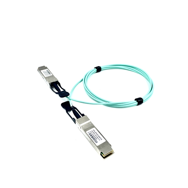
In 1966, Kao proposed that it would be possible to make a low-loss optical fiber using impurity-free silica glass (SiO2). (1) After subsequent technological develop-ments, a low loss of 17 dB/km was demonstrated by Keck et al. in. 1930s-1950s – Fiber Bundles for Imaging: Researchers started using fiber bundles to transmit images, particularly for medical endoscopes. However, these early fibers suffered from extremely high signal loss—over 1,000 dB/km, making them impractical for long-distance communication. This comprehensive review explores OFC's historical evolution, core principles, components, and versatile applications. Optical fibers, core components of global communication infrastructure, are capable of transmitting data over long. Fiber loss, also called fiber optic attenuation or attenuation loss, refers to the loss of signal between input and output.
Acceptable splice loss in optical fiber is typically considered to be less than 0. The calculated loss budget is an estimate that assumes the values of component losses and does not take into account the uncertainty of the measurement. This testing will ensure that the data necessary to properly evaluate any future system malfunctions will be av nctioning. So, you drop everything and i vestigate. He's right – it is n t working. What is the typical acceptable splice loss for single-mode fiber using fusion splicing? What is the acceptable splice loss for multimode fiber using mechanical splicing? How does fiber alignment affect splice loss? Why is cleaning the fiber important before splicing? What role does the cleaver play. Splice loss refers to the part of the optical power that is not transmitted through the splice and is radiated out of the fibre. The total loss in decibels at the fusion splice is given by the following equation, where Pin is the total power incident on the fusion splice and Ptrans is the.
[PDF Version]
Fiber Optic cable termination is the addition of to each in a. The fibers need to have connectors fitted before they can attach to other equipment. Two common solutions for fiber cable termination are pigtails and fanout kits or breakout kits.
A **rent invoice** for optical cables is an essential document used by telecom providers, data centers, or equipment rental companies to bill clients for the rental of fiber optic cables. Free invoice templates for network cabling contractors built for parts and labor, cable runs, and testing and certification. Download and edit in PDF, Word, Excel, Google Docs, or Google Sheets. See how precision classification can protect your finances and unlock greater strategy. Calculate and analyze tariff impacts in real time with the new Flexport Tariff Simulator. Get. Optical Fibers and Cables: Optical fibers, unassembled or not attached to connectors, are generally classified under HS Code 9001.
The short answer is no - RJ45 connectors are designed for electrical Ethernet signals, while fiber optics transmit light pulses through glass or plastic. However, modern networks often combine both technologies. Fiber optic cables and Ethernet cables are two of the most important data transfer cable standards there are, but with their use cases often crossing paths, and colloquialisms even meaning each name is used interchangeably at times, it's important to know the differences with Fiber Optic Cables vs. It has become an essential component of our daily lives, providing fast and reliable communication over long. Fiber optic cables are made of glass fibers and transmit data using the principle of total light reflection. They are then transmitted through an optical fiber acting as a waveguide, carrying light from one. Well, just like any relationship has a foundation of understanding, a wireless network has fiber cabling underneath that helps people connect to the internet whenever they want to. The other most popular cable type is the Ethernet cable.
[PDF Version]
A hybrid fiber optic cable is a composite cable that integrates traditional glass optical fibers for data transmission with copper wires for electrical power. This innovative design eliminates the need to install separate cables for data and power, streamlining complex deployments. In order to do this, they use some very different types of cables. Obviously, these fiber cables need to be resistant to electricity, which can be difficult as many aerial cables contain high tensile steel (HTS) for tensile strength. Optical technology offers suffi ciently significant advantages to power systems environments so that, to date, electricity industries all over the world have either seriously con sidered or indeed utilised a range of optical systems. There are also disad vantages and drawbacks. The difficul ty. I need to know is there a Code and/or Standard prohibiting the placement of Communication fiber in the same conduit as power for Safety reasons. Some primary examples include optical ground wire (OPGW) and all-dielectric self-supporting (ADSS) fiber optic cables, which were both introduced over 30 years ago.
[PDF Version]Contact us for competitive quotes on any of our power communication and smart grid products
Get a Quote