
OTDRs display trace results by plotting reflected and backscattered light versus distance along the fiber, characterizing any reflective and non-reflective events in a fiber link. These reflections, known as Fresnel reflections, are meticulously measured by the OTDR to pinpoint the location of these events within the fiber link. Due to the inherent structure of the fiber and microscopic imperfections within the glass, a small portion of the light pulse scatters in various. An optical time-domain reflectometer (OTDR) is an optoelectronic instrument used to characterize an optical fiber. The OTDR is also commonly used to create a "picture" of fiber optic cable when it is newly installed. However, its value lies not only in taking measurements but also in correctly interpreting the records (traces) it generates.
The document discusses various multiplexing techniques, including frequency division multiplexing (FDM), time division multiplexing (TDM), wavelength division multiplexing (WDM), and code division multiplexing (CDM). Multiplexing in data communications is a method that combines multiple signals or data streams into one signal over a shared medium. This process allows for efficient use of resources and can significantly increase the amount of data that can be sent over a network.
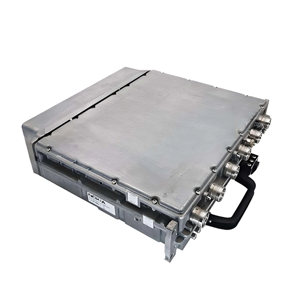
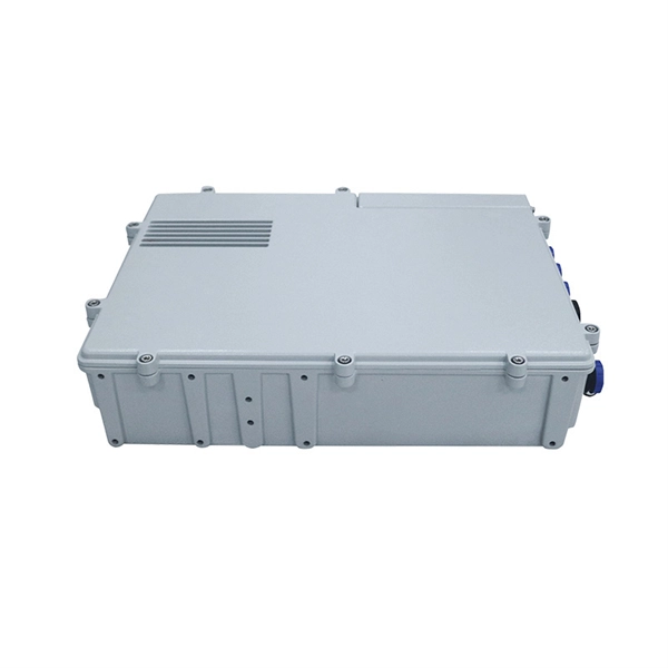
For most packages, the processing time at a distribution center is between 24-48 hours. During this time, the package is sorted, scanned, and dispatched to a carrier for delivery. However, this timeframe can vary depending on the factors mentioned above, such as shipping method. The manufacturing process focuses on precisely assembling these elements into a safe, reliable, and long-lasting unit. It all begins with raw materials. Most enclosures are made from sheet steel, galvanized steel (for corrosion resistance), or specially rated plastic composites. Modern distribution and fulfillment centers serve as the operational heart of the supply chain, where goods are received, stored. Packages end up there after a missed delivery attempt, a hold request, or a redirect, and the process is straightforward once you know where to go and what to bring. For LTL and FTL shipments, it can take up to 10 days.
[PDF Version]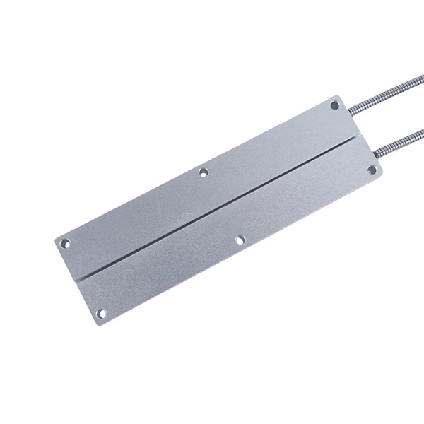
A straightforward way of obtaining selective protection is to use time grading. The principle is to grade the operating times of the relays in such a way that the relay closest to the fault spot operates first. Calculate pickup values, timing curves, coordination time intervals (CTI), and test injection currents for overcurrent (50/51), differential (87), distance (21), and directional (67) protective relays. Accurately measuring the action time is a crucial step to ensure the reliability and. For successful protection coordination, relay working times must be accurately calculated since overcurrent relays activate when circuit current exceeds a predetermined threshold limit. The free online Time Overcurrent Relay Calculator lets electrical engineers immediately calculate relay operate. This calculator evaluates time-current coordination between two protective overcurrent relays — typically a downstream relay closer to the load and an upstream relay closer to the source — at a specified fault current level.
[PDF Version]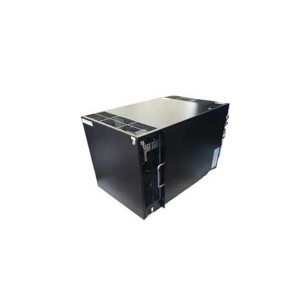
Protective circuit functional testing, including lockout relay testing, must take place immediately upon installation, every 2 years thereafter, and upon any change in wiring. THEY SHOULD BE GIVEN FIRST LINE MAINTENANCE ATTENTION. ” relay may only need to operate for 0. But failure to operate as intended can result in extensive damage, extended power outages, and loss of life. NETA. The testing and verification of relay protection devices can be divided into four groups: Type tests are needed to prove that a protection relay meets the claimed specification and follows all relevant standards. Acceptance tests fall into two categories : (i) On new relays which are to be used for the first time. Features: Durable with no moving parts, ideal for modern grids.
The first experiments in were conducted by beginning in 1894. In 1895–1896 he invented the, which was initially a wire suspended from a tall wooden pole. He found that the higher the antenna was suspended, the further he could transmit, the first recognition of the need for height in antennas. Radio began to be used commercially for.
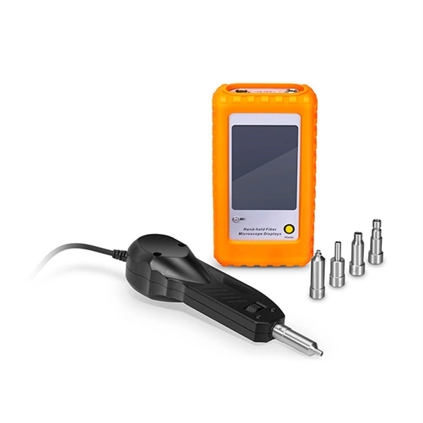
The JDSU MTS-4000 OTDR is a small, compact and handheld test platform designed for all phases of the network lifecycle, from the installation to the maintenance of Access /FTTx networks and triple-play services. Modular in design, the MTS-4000 offers field service technicians the highest. MTS-4000 V2 optical reflectometer package with a 4126A singlemode module For any questions, contact us via our contact form. The system. We are dealing with JDSU MTS 4000 OTDR and our product is made up of good quality.
Contact us for competitive quotes on any of our power communication and smart grid products
Get a Quote