
Complete IEC 62305 lightning protection guide covering risk assessment (Part 2), LPS classes I-IV, rolling sphere method, down conductors, air termination, and SPD selection. We offer a complete, integrated capability to provide lightning protection solutions for towers, antennas, and other structures. Our products can. – Lightning attraction effect and power supply mode of communication towers – Sensitivity of equipment – Economic benefits Definition and statistics of lightning strike intensity Thunderstorm Day Nk: Nk < 25 days – low risk area Nk > 25 days – medium risk area Nk > 40 days – high-risk area Nk > 90. This case study analyzes a 220 kV–400 kV substation connection using 36 power transmission towers, 2. With this in mind, LEC has created a solution which makes it easy to implement a complete lightning. Recommendation ITU-T K. The need of protection is obtained from the methodology contained in IEC 62305-2, which is used to determine the relevant lightning protection. Investing in proper lightning and surge protection for communications infrastructure can avoid these risks and disruptions.
[PDF Version]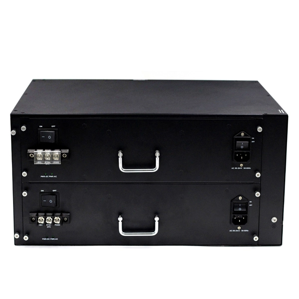
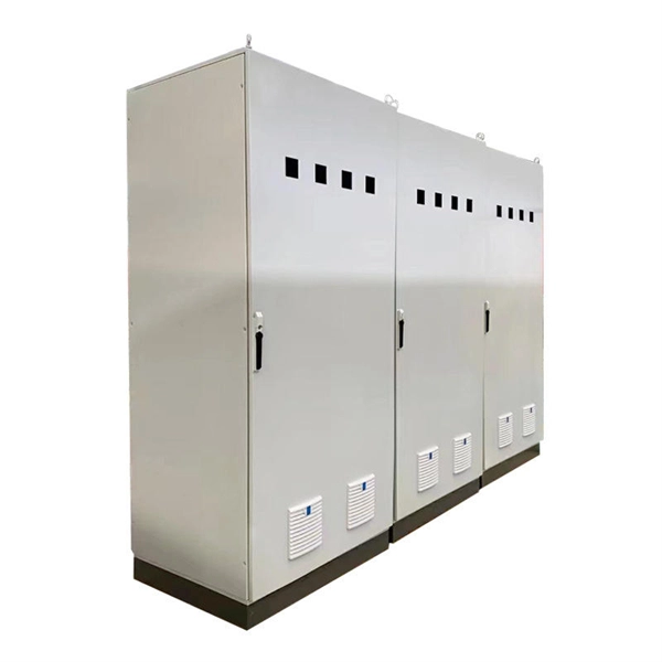
The metal box of the distribution box, the electrical installation board, and the metal base and casing of the electrical appliances in the box must be grounded. The protective neutral wire should be reliably connected through the terminal board. Are you expecting any of those 6 switches will require a neutral connection? @RobertChapin Does not. But it does require panelboard with a neutral that has more than 10 percent of its overcurrent devices rated 30 amperes or less to be protected against overcurrent by a device that has a rating not greater than that of the panelboard. It includes isolator, RCCB (Residual current circuit breaker) or RCD (Residual-current device) devices, protective fuses or MCB's (Miniature Circuit Breaker).
The article provides an overview of protective relaying principles and their applications for high-voltage power system components. It covers the protection methods for generators, transformers, buses, and transmission lines using various relay types to detect and isolate faults efficiently.

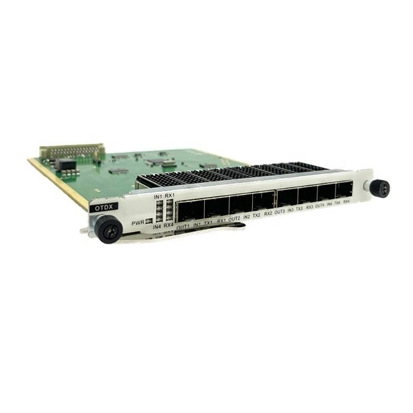
Remove the CPU module from the relay housing and set aside. Be certain to align the printed circuit board with the card guides in the housing. Always use antistatic bags for transporting modules Remove AC power and DC power from the PCD before removing, installing or wiring any of the PCD modules. Consult. What are the steps for safely removing and reinstalling a PLC CPU module? Safe removal and reinstallation of a PLC CPU module requires strict adherence to proper procedures to prevent equipment damage, data loss, or safety hazards. Consult the most recent PCD Instruction Book for details on programming the new CPU to suit your requirements. 0 or Modbus ASCII communications, protocol documentation is available. 1. 1 INTRODUCTION TO THE UR The GE Universal Relay (UR) series is a new generation of digital, modular, and multifunction equipment that is easily incorporated into automation systems, at both the station and enterprise levels. In particu-lar, one will find: General information with regard to design, configuration, and operation of SIPROTEC 4 devices are set out in the SIPROTEC 4 System Description /1/.
[PDF Version]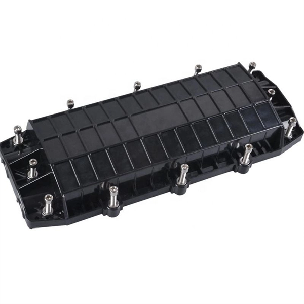
Polyethylene (PE) is the material of choice for use as an aerial OSP cable jacket. The performance of raw PE can degrade rapidly through exposure to sunlight but the addition of carbon black to the cable jacket absorbs the UV light to protect the plastic jacket of the cable. Fiber optic cables enable high-speed, long-distance data transfer, forming the backbone of modern communication. Yet, outdoors, they face temperature swings, moisture, UV exposure, rodents, and human interference. This guide covers how to. Deploying fiber above ground on poles or towers removes the need for underground digging and is particularly useful when the ground is uneven, rocky or both. Some are self-supporting, requiring no separate messenger wire between poles to support the cable's weight. As the leading world manufacturer of fiber optic cable, AFL is uniquely positioned to provide a full line of. Aerial work mixes mechanical engineering (span, sag, tension), careful selection of cable types (ADSS, figure-8, lashed) and a disciplined safety-first attitude.
[PDF Version]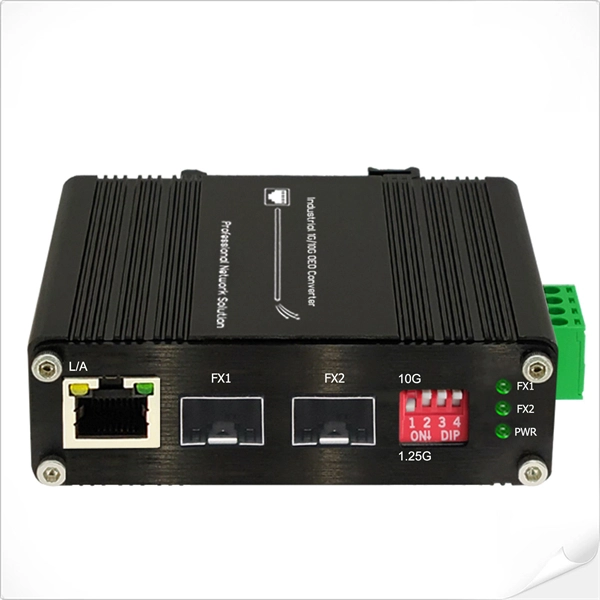
Distance relays, also known as impedance relay, differ in principle from other forms of protection in that their performance is not governed by the magnitude of the current or voltage in the protected circuit but rather on the ratio of these two quantities.OverviewIn, a protective relay is a device designed to trip a when a is detected. The. Electromechanical protective relays operate by either, or. Unlike switching type electromechanical with fixed and usually ill-defined operating voltage thresholds. Electromechanical relays can be classified into several different types as follows: "Armature"-type relays have a pivoted lever supported on a hinge or knife-edge pivot, which carries a moving contact. These relays may.
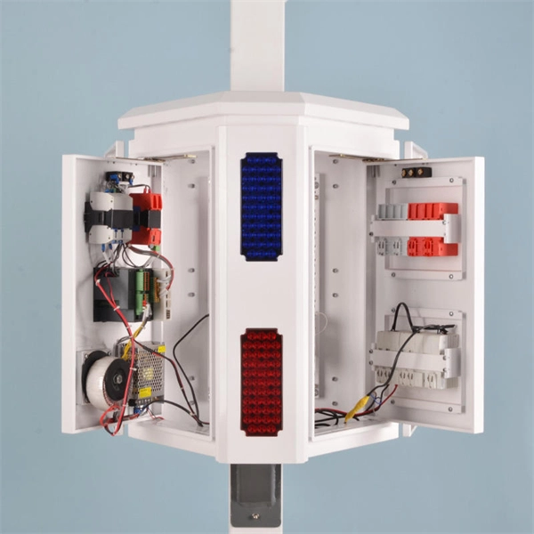
A power over ethernet surge protector, also known as a PoE surge protector (Surge Protective Device), is designed to protect Ethernet-based systems from transient overvoltage caused by lightning activity, switching operations, or electrical disturbances in nearby equipment. It is widely used in IP-based systems such as IP cameras, wireless access points, and network switches, where both. By sending data and electrical power over a single cable, PoE simplifies installations and powers devices such as IP cameras, wireless access points and VoIP phones. But with great convenience comes vulnerability. Protect your network devices from lightning strikes and ESD. It, therefore, requires special. This article is the first in the "Protect Your Ports! Top Design Tips to Keep Your Communications Connected" series from Littelfuse. It's now widely used in both everyday and industrial settings.
[PDF Version]
A straightforward way of obtaining selective protection is to use time grading. The principle is to grade the operating times of the relays in such a way that the relay closest to the fault spot operates first. Calculate pickup values, timing curves, coordination time intervals (CTI), and test injection currents for overcurrent (50/51), differential (87), distance (21), and directional (67) protective relays. Accurately measuring the action time is a crucial step to ensure the reliability and. For successful protection coordination, relay working times must be accurately calculated since overcurrent relays activate when circuit current exceeds a predetermined threshold limit. The free online Time Overcurrent Relay Calculator lets electrical engineers immediately calculate relay operate. This calculator evaluates time-current coordination between two protective overcurrent relays — typically a downstream relay closer to the load and an upstream relay closer to the source — at a specified fault current level.
[PDF Version]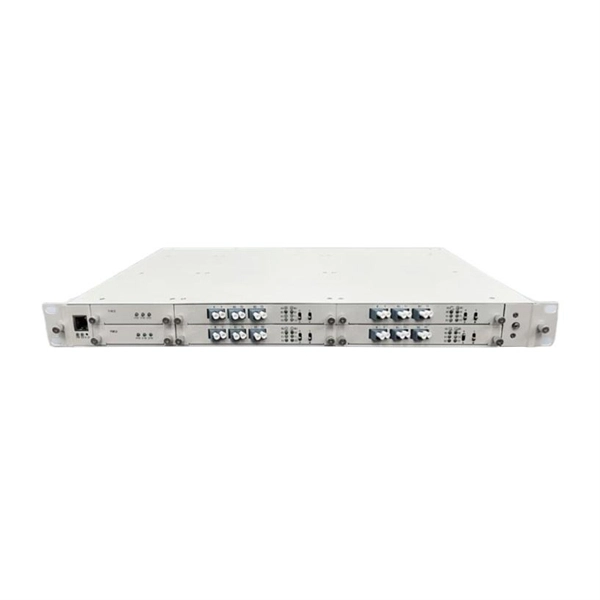
Electromechanical relays can be classified into several different types as follows: "Armature"-type relays have a pivoted lever supported on a hinge or knife-edge pivot, which carries a moving contact. These relays may work on either alternating or direct current, but for alternating current, a shading coil on the pole is used to maintain contact force throughout the alternating current cycle. Because the air gap between t.
A comprehensive protection relay (or integrated protection relay) is a smart electrical device that combines multiple protection functions to monitor power systems (e., generators, transformers, motors, transmission lines) and quickly isolate faults to ensure safety. It features modular. IEEE/IAS/I&CPSD Protection & Coordination WG Chair Jacobs Canada, Calgary, AB rasheek. Currently residing in Denver, Colorado. Previous experience in designing low voltage and medium voltage switchgear, relay panels and custom control panels as an Electrical Engineer at ESSMetron, Denver CO. SIPROTEC 7SD80 delivers selective line protection for power cables and overhead lines up to 24 km, supporting all starpoint configurations.
Contact us for competitive quotes on any of our power communication and smart grid products
Get a Quote