
Some early busbar protection configurations applied a low impedance differential system that has a relatively long operation time, of up to 0. The foundation of most modern configurations is a differential system using either low impedance biased or high impedance. The choice of protection technique used for a specific busbar depends on the protection requirements for speed and security, balanced against the cost of implementing a specific solution, and the operating requirements for a specific bus. In the early days of power system development no separate protection device was used for busbar protection. Remote end-line protections served as the main. This comprehensive guide explores the technical requirements, installation best practices, and protection coordination strategies for MCCB-busbar connections. Whether you're designing a new switchgear assembly or maintaining existing distribution panels, understanding proper connection methods. segregated short-circuit protection, control, and supervision of single busbars.
[PDF Version]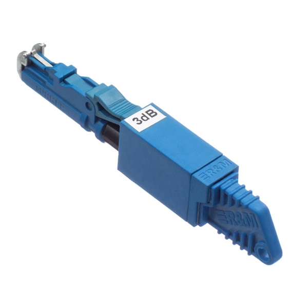
ABB's busbar protection is designed for phase-segregated short-circuit protection, control, and supervision of single busbars. GE Multilin provides protective relays that support all busbar protection techniques, including overcurrent, high-impedance differential, and percentage (low-impedance) differential. Current Differential Protection: This protection method connects CT secondaries in parallel and. This article discusses a software based substation protection, automation, and control system (PACS), iSAS, developed by LYSIS LLC, Russia which is was at that time under trial operation at the 110/10 kV “Olympic” substation in the town of Surgut in northwest Siberia. The philosophy of iSAS is. A busbar is a strip or bar of copper, brass or aluminum that conducts electricity within a switchboard, a substation or a battery bank. Its purpose is to conduct a substantial current of electricity.
[PDF Version]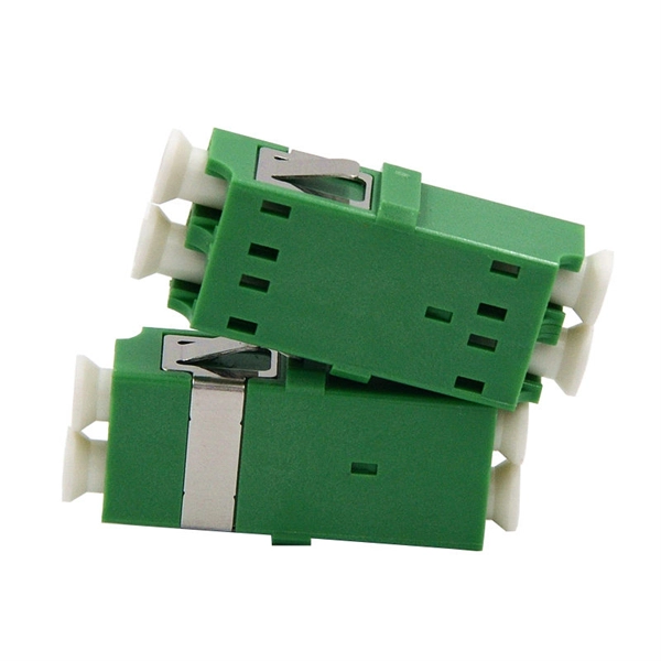
The IEC 61439-1 sets the thermal limit in busbars working at the maximum working load. Here, 140°C (which is 105K over the ambient temperature of 35°C) is the upper safe temperature limit. Continuous, real-time busbar temperature monitoring and hot spot detection for MV & HV switchgear, substations and power plants — EMI-immune, calibration-free, fully SCADA-integrated. Thermal monitoring locations include: Eaton Exertherm CTM solution for MV switchgear. Standards mandate that busbars, when carrying their rated continuous current for extended periods, must not experience excessive temperature rise.
ABB's busbar protection is designed for phase-segregated short-circuit protection, control, and supervision of single busbars. One B90 is used for each phase, and processes only the AC signals for that phase, eliminating. SIPROTEC V virtualizes substation protection & control, scaling up to 60 IEDs on one server with proven algorithms, IEC 61850 compliance, and AI-ready architecture. The SIPROTEC 7SX85 is a modular universal protection device. Hitachi Energy's range. This product is a 25kVA single-phase oil-immersed pole-mounted transformer, specifically designed as a distribution device for outdoor distributed load applications. Featuring a fully sealed oil-immersed structure, it offers convenient installation, reliable operation, and maintenance-free. A busbar is a strip or bar of copper, brass or aluminum that conducts electricity within a switchboard, a substation or a battery bank.
[PDF Version]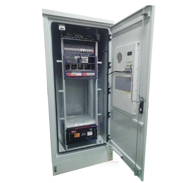
This guide provides a comprehensive overview of various transformer protection schemes and offers recommendations for relay selection, coordination, and settings. Another important standard is the IEC 61850, which focuses on communication protocols for substation automation systems. Table 1 – Transformer fault types/protection methods 1. In HV (High Voltage) and MV (Medium Voltage) substations, relay protection safeguards critical assets such as transformers, circuit breakers, and lines. • If current penetrates the limits of the thermal damage curve, insulation damage may occur.
A protective relay operates by continuously monitoring electrical parameters, detecting abnormalities, making decisions, and triggering circuit breakers to isolate faulty sections. Engineering use: Relays are used on feeders, transformers, buses, motors, generators, and transmission lines to protect equipment and improve system. A protective relay is an intelligent electrical device designed to detect faults in power systems and initiate corrective actions such as tripping a circuit breaker. They are intended to quickly identify a fault and isolate it so the balance of the system continue to run under normal conditions. For example, unselective protection operation during a medium voltage network fault will cause an outage for an unnecessarily large number of consumers. : 4 The first protective relays were electromagnetic.
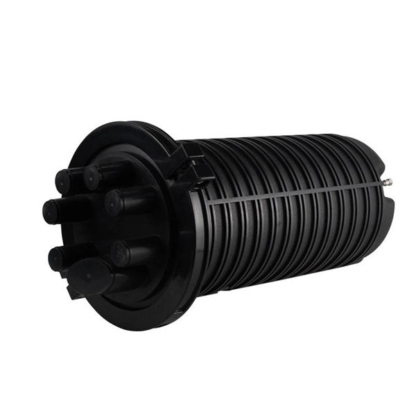
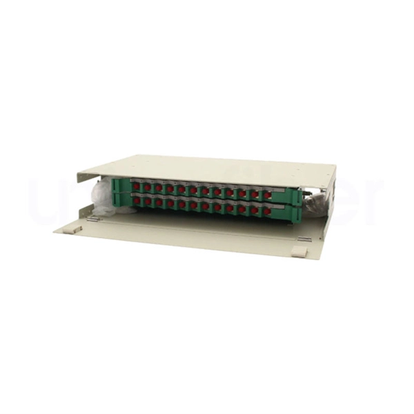
Fiber distribution box, also known as fiber optic distribution frame, is an essential component in fiber optic communication networks. In modern FTTH and FTTx networks, several types of fiber management hardware ensure reliable optical connectivity from the central office to the end user. This guide demystifies ODF, exploring their design, core functions, types, and how they. In modern optical communication networks, especially FTTH (Fiber to the Home) systems, the fiber distribution box plays a crucial role in ensuring stable, efficient, and reliable signal distribution. As data centers, enterprises, telecom operators, and smart-building infrastructures deploy increasingly dense fiber links, ODFs provide the structured.
Contact us for competitive quotes on any of our power communication and smart grid products
Get a Quote