
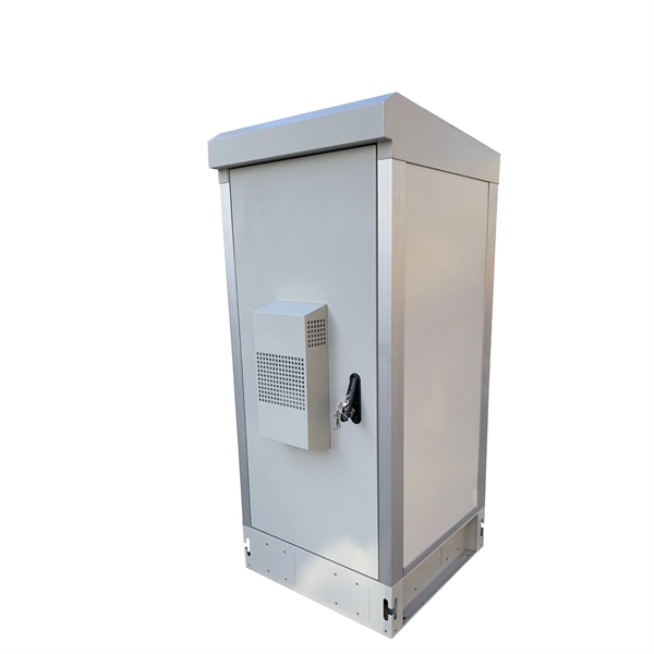
The BBU3900 is a high-performance baseband processing unit that improves signal stability, processing speed, and power efficiency in fiber optic systems, offering better compatibility and performance compared to the WD2BBUC. About This Document About This Document Introduction This document describes the BBU3900 hardware, such as boards, module, ports, cables, and connectors, and the functions of the hardware. Product Version The following table lists the product versions related to this document. • Only when the BBU install in TP48200A and APM30H cabinets, subrack cable claws are configured. Preferentially configured in S19.
This document describes how to check the switch interface or port status and how to locate an interface physically down fault and restore the interface to the up state. Hardware failures: include hardware. Problem: All optical ports cannot be connected, and the indicator lights are not on. Perform a. HUAWEI S Series Switch-Handle an Optical Interface's Failure to Go Up video provides guidance on how to handle an optical interface's failure to go Up. During use, reading optical module information helps understand its real-time operating status, enabling faster troubleshooting of link abnormalities. Sample Output: (Can see link down and not receiving any power from the neighboring device) Or can do filtering:. I'm trying to find an explanation for why when an optical gig port on an NE40 is configured with autoneg disabled, the interface still passes traffic without error, but causes the connected ADVA interface to show as down, while it is also passing all the traffic it is supposed to.
[PDF Version]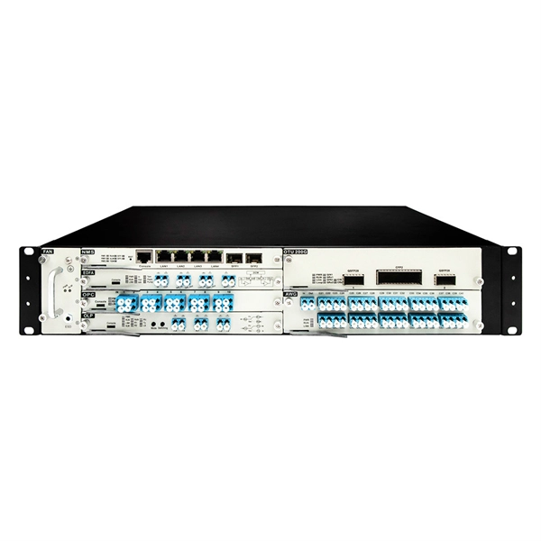
A simple solution is to combine a Corning USB “A to receptacle-A” USB 3. Optical™ Cables by Corning with a short, off-the-shelf jumper cable that has a USB “A” plug on one side and the particular connector your end device requires on the other. 0 A female port of the AOC Cable. Vielen Dank für den Kauf dieses Optischen USB 3. Es unterstützt größere Distanzen als herkömmliche Kupferkabel, ist deutlich flexibler und leichter und daher optimal. A workaround would be to connect the USB 3. Once connected, check the Windows Device Manager to verify the devices that have been successfully connected through the device. The USB active optical cables are designed to be compliant with SuperSpeed USB and SuperSpeed+ USB electrical specifications, offering seamless interoperability between existing USB 3. 1 hosts, hubs and devices, ensuring a trouble-free plug-and-play experience. The USB AOC address the. Connect the USC-CC32 Type C device connector to the USB Hub.
[PDF Version]
To connect one device having FC/PC interface with one FC/APC interface, an option is to use a piece of optical patch cord that has FC/PC and FC/APC at its ends. FC/PC and FC/APC connectors are widely used in fiber optical devices, equipment and systems. It is a common problem many people have when they use those two types of connectors: those connectors can not join with each other, because their tips. Today, this post will introduce APC, UPC, and PC fiber connector types, which are classified based on the different angle polished fiber end face shapes. Next, the post will introduce the polish style, structure, difference, application, and usage attention of these connectors. Each type varies by shape, polish (APC, PC, or UPC), and return loss performance, which affect PC, UPC, and APC Polish Styles: What's the. A fiber optic patch cord, also known as a fiber optic patch cable or fiber jumper, is a length of fiber optic cable capped at both ends with connectors that allow it to be rapidly and conveniently connected to an optical switch, router, or other telecommunication/network equipment.
[PDF Version]
The solution is to unplug the fiber and reinsert it into the SFP module interface until a “click” sound is heard, indicating the fiber connector and SFP module are properly connected. There are two primary reasons why an SFP module might become stuck in a port: The SFP is wedged in the cage: This can occur due to slight. These faults can be identified and located through visual inspection and the built-in DDM function of the optical module. However, locating the fault does not always mean it can be resolved—if the hardware is damaged, the issue can only be fixed by replacing the module. Common physical layer faults. Have you ever experienced an unexpected network outage due to the failure of an SFP/SFP+ optical transceiver? Network outages can bring your ability to communicate and work to a halt, and your IT team will likely be frantically looking for a solution. Contaminated connectors, damaged fiber, incompatible module parameters, poor signal strength. Choosing LINK-PP SFP Transceivers often reduces.
[PDF Version]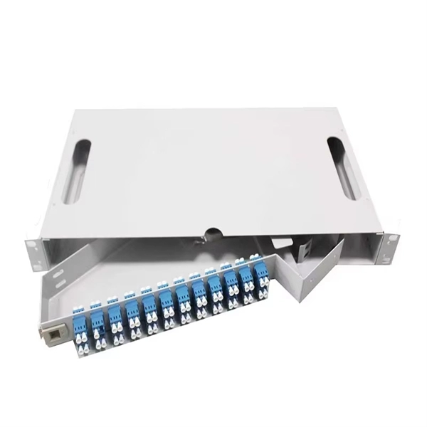
The fundamental calculation formula is: Total patch cords = Total number of device ports × Connection factor Where the connection factor depends on the connection method: 2. Scenario-Based Calculations The redundancy factor is typically 0 (no redundancy) or 1 (1:1 redundancy). the list of patch cords that fulfill the requirements and can be made to order. It covers LC connectors, LC patch cables, uniboot designs, armored. Premium-Line 19” Rack mountable fiber optic patch panel is designed for both patching and splicing, accepts whole range of adapters including SC, ST, FC, LC adapters. 2 * Rear cable entries accommodate cables with diameter below 10mm. More detailed calculation is available in our software. Accurate length fixing is a crucial aspect in planning, with the goal of ensuring efficient, safe, and future-proof implementation of fibre optic patch cords. They are manufactured and tested in compliance with TIA 604 (FOCIS), IEC 61754 and YD/T industry standards.
[PDF Version]Contact us for competitive quotes on any of our power communication and smart grid products
Get a Quote