
Complete IEC 62305 lightning protection guide covering risk assessment (Part 2), LPS classes I-IV, rolling sphere method, down conductors, air termination, and SPD selection. We offer a complete, integrated capability to provide lightning protection solutions for towers, antennas, and other structures. Our products can. – Lightning attraction effect and power supply mode of communication towers – Sensitivity of equipment – Economic benefits Definition and statistics of lightning strike intensity Thunderstorm Day Nk: Nk < 25 days – low risk area Nk > 25 days – medium risk area Nk > 40 days – high-risk area Nk > 90. This case study analyzes a 220 kV–400 kV substation connection using 36 power transmission towers, 2. With this in mind, LEC has created a solution which makes it easy to implement a complete lightning. Recommendation ITU-T K. The need of protection is obtained from the methodology contained in IEC 62305-2, which is used to determine the relevant lightning protection. Investing in proper lightning and surge protection for communications infrastructure can avoid these risks and disruptions.
[PDF Version]
It is generally installed in the socket circuit of each household distribution box and the power supply line of the whole building distribution box, the latter is dedicated to prevent electrical fire. Leakage protection is leakage maintenance. After the human body contacts the leakage, it will take the initiative to disconnect and maintain the. Selecting and installing the right protective enclosure ensures long-term electrical safety in demanding environments. A robust waterproof distribution box shields sensitive components from moisture, dust, and mechanical impacts. This guide primarily analyzes structural engineering characteristics. - **Power inlet connection**: Generally, a leakage protector has two inlet terminals, marked as L (live wire) and N (neutral wire). When wiring, make sure the stripped length of the wire is.
Power system protection relays can be categorized into different types of relays. Types of Protective Relays: Protective relays are categorized by their mechanism (electromagnetic, static, mechanical) and function. This article covers various types of protective relays, such as overcurrent, directional, and differential relays, highlighting their operating characteristics and applications in electrical systems. Its main purpose is to safeguard electrical equipment like transformers, generators, and transmission lines from damage due to. In electrical engineering, a protective relay is a relay device designed to trip a circuit breaker when a fault is detected. Long term cost reduction (TCO) for trainings and maintenance by reduce variety of relays A fast and selective arc fault mitigation for air-insulated LV & MV switchgear and Relion protection and control relays and sensor. A protection relay is a crucial component of electrical systems that safeguard infrastructure, employees, and equipment from electric problems and malfunctions.
[PDF Version]
Electromechanical relays can be classified into several different types as follows: "Armature"-type relays have a pivoted lever supported on a hinge or knife-edge pivot, which carries a moving contact. These relays may work on either alternating or direct current, but for alternating current, a shading coil on the pole is used to maintain contact force throughout the alternating current cycle. Because the air gap between t.
The IEC 61439-1 sets the thermal limit in busbars working at the maximum working load. Here, 140°C (which is 105K over the ambient temperature of 35°C) is the upper safe temperature limit. Continuous, real-time busbar temperature monitoring and hot spot detection for MV & HV switchgear, substations and power plants — EMI-immune, calibration-free, fully SCADA-integrated. Thermal monitoring locations include: Eaton Exertherm CTM solution for MV switchgear. Standards mandate that busbars, when carrying their rated continuous current for extended periods, must not experience excessive temperature rise.
This leakage current is measured in milliamps 'mA' (1/1000 amp) and if the leakage current reaches a pre-determined level, usually 30 mA '0. 03 A' the device will operate and isolate the supply from the circuit. In addition to fault protection (protection in cases of indirect contact), residual current protective devices with rated residual currents up to 30 mA also provide “additional protection” in cases of direct contact. Fires caused by ground-fault currents can also be prevented at a very early stage. Subsequently, new types of RCD have been developed. This article. RCDs, or Residual Current Devices, are designed to monitor the electrical current flowing in a circuit and automatically disconnect the power supply if it detects an imbalance between the live and neutral conductors.
Guidance on settings for the 132kV system is given in CP338, and for the 33kV and 11/6. Relay protection is essential to ensure the stability, reliability, and safety of electrical power systems. Protective relaying is the backbone of fault detection and system isolation in As transmission systems grow increasingly complex with integration of. This document states the Electricity North West Limited policy for protection for all high voltage systems. It covers standard codes, wiring practices, and norms for protecting generators, transformers, and lines, and provides detailed. Abstract: Covered in this recommended practice is the protection of bus and switchgear used in industrial and commercial power systems. Protection selectivity is partly considered in this report and could be also re-evaluated.
Electromechanical protective relays operate by either, or. Unlike switching type electromechanical with fixed and usually ill-defined operating voltage thresholds and operating times, protective relays have well-established, selectable, and adjustable time and current (or other operating parameter) operating characteristics. Protection relays may use arrays of, shaded-pole, magnets, operating and restraint coils, solenoid-type operators, telephone-relay contacts.

This article explores the current trends, innovations, and market insights surrounding relay protection, focusing on tools like the secondary injection test set, three-phase relay test set, and single-phase relay test set. able sources such as wind and solar. These clean energy sources, connected through inverters and flexible transmission systems, are transforming traditional grids based on synchronous generators into more flexibl cant challenges to system stability. A big difference between conventional electromechanical and static relays is how the relays are wired. Numeric. IEEE/IAS/I&CPSD Protection & Coordination WG Chair Jacobs Canada, Calgary, AB rasheek. com IEEE Southern Alberta Section PES/IAS Joint Chapter Technical Seminar - November 2016 Protective Relays - Technical Seminar Nov 2016 - Copyright: IEEE 2 Abstract: Protective relays and devices. At the core of a modern substation lies the protection relay: an intelligent electronic device (IED) that plays a critical role in maintaining the stability of the power grid by continuously monitoring voltage, current, frequency, and phase angle.
[PDF Version]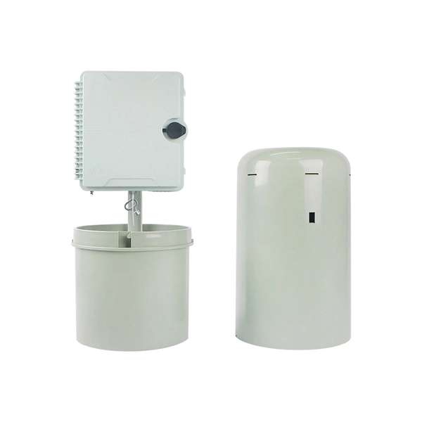
The best distribution box makers in 2025 care about safety. They add smart features and save energy to keep your home or business safe. Top brands like Schneider Electric, DOHO Electric, and ABB have certified products. Here, the report highlights some of the top electrical enclosure manufacturers making significant impacts in global operations. Hammond Manufacturing Hammond Manufacturing is a top manufacturer of high-quality electrical enclosures, racks, cabinets, and transformers for industrial and commercial. As a leading electrical box manufacturer with more than 20 years of industry and R&D experience, SKKBO provides versatile and high-quality customized electrical box solutions for various countries. You also want reliability and cool new features.
Contact us for competitive quotes on any of our power communication and smart grid products
Get a Quote