
Single-mode fiber is an optical fiber designed to carry one primary path, or mode, of light through a very small glass core. Modes are the possible solutions of the Helmholtz equation for waves, which is obtained by combining. Network cables, known as fiber optics, allow data to be transmitted using pulses of light that travel along the fiber. Glass or plastic are often used to make these fibers. Two main types dominate network design: multimode fiber and single-mode fiber. The wrong fiber can lead to: Costly Overengineering: Using single mode fiber for a 50-meter data center link. This comprehensive guide explores Single-Mode Fiber Optic Cable, covering technical specifications, deployment scenarios, and best practices to help you optimize your fiber infrastructure for maximum performance and reliability.
The loss value of a pigtail connector and its associated splice with matching mode field diameters should not exceed 0. Pigtail traces for all. at system. Corning recommends that all fiber optic systems be tested to a minimum set of standards. So, you drop everything and i vestigate. FOA standards align with IEC and TIA, giving you clear steps to earn trusted certification. No part of this book may be reproduced or utilized in any form or means, electronic or mechanical, including photocopying, recording, or by any information storage and retrieval system, without pe n optical fiber to a distant receiver. The electrical signal is. To be able to judge whether a fiber optic cable plant is good, one does a insertion loss test with a light source and power meter and compares that to an estimate of what is a reasonable loss for that cable plant.
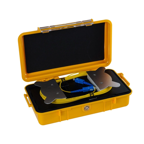
This document outlines the procedure recommended by Panduit for field permanent link loss testing of multimode and singlemode structured cabling systems. It simply means a reduction in optical power, for example the loss caused by a component or an entire cable. The component could be a length of fiber, a splice, a connection made between two connectors or a passive component like an. FOA "Quickstart Guides" are short, simple guides to basic fiber optic tests. References to FOA "1. Launch Fibers are packaged in a rugged, convenient zipper case, designed for use with our T-Pak magnetic / hanger / hook and loop strap. Also known as launch packs or Dead Zone Eliminators used for OTDR (Tier II) testing Fluke Networks Test Reference Cords and Launch Fibers with LC connectors. This Applications Engineering Note (AEN 135) explains and recommends standard measurement methods for characterizing optical fiber system performance.
[PDF Version]
OS1 and OS2 are standard single mode optical cables respectively used with wavelengths of 1310nm and 1550nm with a maximum attenuation of 1 dB/km and 0. OS1 fiber is a tight buffered cable designed for use in indoor applications (such as campuses or data centers) where the. In fiber-optic communication, a single-mode optical fiber, also known as fundamental- or mono-mode, is an optical fiber designed to carry only a single mode of light - the transverse mode. Modes are the possible solutions of the Helmholtz equation for waves, which is obtained by combining. This comprehensive guide explores Single-Mode Fiber Optic Cable, covering technical specifications, deployment scenarios, and best practices to help you optimize your fiber infrastructure for maximum performance and reliability. Glass or plastic are often used to make these fibers. Although they can do the same job in some instances, the different construction methods make each of them better suited to certain tasks and budgets. That makes picking between single mode and multimode fiber optic cables an.
[PDF Version]
Fiber optic splicing is the process of joining two optical fibers end-to-end. Unlike using connectors, which are designed for frequent connection and disconnection at patch panels, splicing creates a permanent, stable joint with minimal light loss. The optical fiber elements are typically individually coated with plastic layers and contained in a protective tube. Fiber optic cables are the invisible highways of our digital world, carrying massive amounts of data at the speed of light. Fusion Splicing: This method involves aligning the ends of the two fiber optic cables and then fusing them together using heat. This creates a permanent and low-loss connection. Thin strands of glass bundled in cables and stretched across continents and oceans make possible much of what we take for granted today, such as the Internet, Zoom calls, electronic. The existing 2" conduit contains 4x 1/0 XLPE cable (rated for direct-burial), so I plan on pulling outdoor rated, non-metallic fiber through the same conduit. My original plan was to trench new conduit and run CAT8, but given that the existing run is all "customer side" and installed by the former.
[PDF Version]
FOA procedures, such as OFSTP-7 (single-mode) and OFSTP-14 (multimode), align with TIA and IEC standards. Fiber Optic Testing Testing is used to evaluate the performance of fiber optic components, cable plants and systems. As the components like fiber, connectors, splices, LED or laser sources, detectors and receivers are being developed, testing confirms their performance specifications and helps. ondition of the cabling system and its components with an op cal time domain reflectometer (OTDR). The condition of the fibre end fac g with an OLTS and an OTDR and have obtained a certificate as proof thereof shall execute the tests. 11 Optical Fiber Systems Subcommittee and published in September, 2022. They describe how to set a '0 dB' reference, control mode power distribution, and use proper wavelengths.
Contact us for competitive quotes on any of our power communication and smart grid products
Get a Quote