
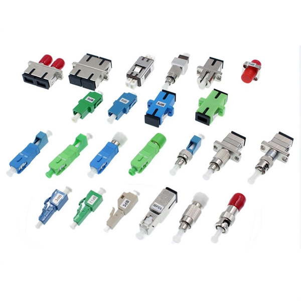
The normal recommendation for fiber optic cable is the minimum bend radius under tension during pulling is 20 times the diameter of the cable (d). Burst pressure ratings for pigtails are determined at room temperature with the hose in a straight line. A safety factor of 4:1 or 5:1 should be used for normal applications. The connectors work in a frequency range of up to 6 GHz and guarantee maximum component density thanks to their low overall height of 2. 5mm and a space requirement of just 3mm². We offer over 6,000 different Types and Sizes of RoHS Compliant Liquid Tight Strain Relief Fittings, Cord Grips, Cable Glands, Circular Connectors, Conduit System, Industrial Enclosures and Other Related Cable Management Products which are rated the best in the industry. From Table 3, the formula is “F x OD” and, from.
Learn the step-by-step network patch panel and keystone jack wiring methods, including essential tools, T568A/B wiring sequences, and tool-free installation tips. This guide walks you through how to build a dependable patch panel system—step by step. We'll cover technical best practices, procurement tips, real-world challenges, and answers to common questions. Use a small yellow tool or wire stripper to remove the outer jacket of the network cable. Insert the network cable into the corresponding terminal slots according to the specified. When you're building a network, it's often ideal to use a patch panel to direct cables and organize long Ethernet runs — especially if they go through walls, floors, and/or ceilings. Unlike active devices that process data, a patch panel simply provides structured termination points for each Ethernet cable run, creating a clean, scalable. Wired networks can still deliver stable, high-performance connectivity—and a Cat5e patch panel helps centralize and manage incoming Ethernet cables.
[PDF Version]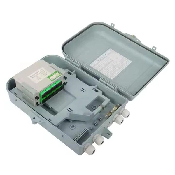
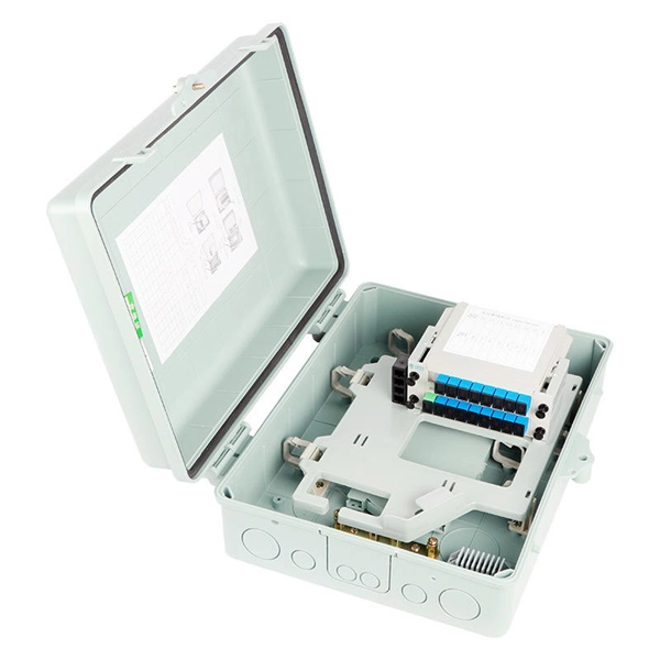
Learn how to install a fiber optic termination box step-by-step for FTTH projects. Covers mounting, splicing, routing, labeling, and testing for indoor/outdoor use. Strip the cable the required length, minimum 1 meter or more, to establish easy and safe installation with enough buffer. FTTP or fiber To The Premises applications have reinforced the importance of reliable and stable fiber optic terminations. It functions as a junction between the incoming fiber cable and the outgoing customer-side fiber cable, where one fiber can be spliced, patched. A common question we receive is: How do you use a fiber-optic termination box? We recommend using a termination box if you're ordering an assembly with more than two strands. It helps keep your connectors free from contamination and dust, while also keeping your assembly neat and organized. They also require the optical fibers to be beautiful.
[PDF Version]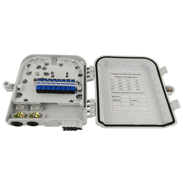
The Integrated Routing (IR) single element tray is manufactured from ABS and finished to a high specification to eliminate the risk of snagging or microbends. All retaining tabs on the tray have radius edges and rounded corners where fibre may pass. Note: this means safety OR seat belt is searched as (safety OR seat) AND belt. Each word automatically includes plurals and close synonyms. The trays are engineered for use with indoor or outdoor splice hardware with both loose tube and tight-buffered optical cable designs. Designed as the central point to safely route, terminate, and store exposed fibers, each splice tray are engineered with. This 12 core Fiber Optic Splice Tray (ODF module) is an integration melting module 12 core fiber optic splice tray.
Disconnect the point wire from the negative (-) terminal of the coil. The Ignitor does not require any modification to the distributor. In this guide, you'll learn the process of breaking down and rebuilding a distributor using new parts. The use of a propane torch is mentioned to. Manuals through 2025 now available! Our trusted friends have launched a new website named LEMON, which has newer manuals. LEMON is the spiritual successor to CHARM, I recommend you try it! Link: lemon-manuals. The. The main function of the car distributor is to provide the high voltage current produced by the secondary coil to the correct spark plugs in the correct firing order and at the correct time.
Contact us for competitive quotes on any of our power communication and smart grid products
Get a Quote