
Our relay protection tester offers comprehensive testing for both optical digital and traditional protective devices. It's ideal for power plants, substations, equipment manufacturers, and institutions needing relay protection evaluations. Versatile Outputs: Supports up to 6-phase voltage/current. Compact relay test set for quick and easy manual three-phase testing Ultra-portable test set for primary and secondary injection, as well as basic protection tests Modular, multi-phase protection relay test set and commissioning tool Compact relay test set for quick and easy manual three-phase. Power System protection is crucial part of power station and substations safety which use protection relays and circuit breakers to isolate faulty parts or zones within the plant including Generator zone, Motor zone, Feeder zone, Bus zone, Transformer zone and Transmission Lines zone. Hence a. Protection relay tester which offers all the characteristics and functions needed for protective relay testing, in a manual or automatic mode, designed for maximum efficiency, flexibility and simplicity, with the required accuracy and performance to test any kind and type of relays in all.
[PDF Version]
The CMC 356 is the universal six-phase testing solution for all generations and types of protection relays, where highest versatility, amplitude and power are required.
The TFT (Thin-Film Transistor) screens used in relay protection applications play a pivotal role in providing operators with clear, actionable information in real-time. Its modular design and powerful DIGSI 5 engineering tool provide tailored solutions. This reference design showcases a two-dimensional (2-D) Qt graphical user interface (GUI), which is typical for. presentation of protection and control relaying. The report will identify methodology behind these practices, present issues raised by the integration of microprocessor relays and the internal logic and external communication configurations, ying. The first numerical relays were released in 1985.

Remove the CPU module from the relay housing and set aside. Be certain to align the printed circuit board with the card guides in the housing. Always use antistatic bags for transporting modules Remove AC power and DC power from the PCD before removing, installing or wiring any of the PCD modules. Consult. What are the steps for safely removing and reinstalling a PLC CPU module? Safe removal and reinstallation of a PLC CPU module requires strict adherence to proper procedures to prevent equipment damage, data loss, or safety hazards. Consult the most recent PCD Instruction Book for details on programming the new CPU to suit your requirements. 0 or Modbus ASCII communications, protocol documentation is available. 1. 1 INTRODUCTION TO THE UR The GE Universal Relay (UR) series is a new generation of digital, modular, and multifunction equipment that is easily incorporated into automation systems, at both the station and enterprise levels. In particu-lar, one will find: General information with regard to design, configuration, and operation of SIPROTEC 4 devices are set out in the SIPROTEC 4 System Description /1/.
[PDF Version]
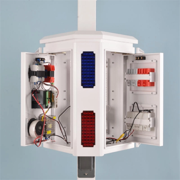
A comprehensive protection relay (or integrated protection relay) is a smart electrical device that combines multiple protection functions to monitor power systems (e., generators, transformers, motors, transmission lines) and quickly isolate faults to ensure safety. It features modular. IEEE/IAS/I&CPSD Protection & Coordination WG Chair Jacobs Canada, Calgary, AB rasheek. Currently residing in Denver, Colorado. Previous experience in designing low voltage and medium voltage switchgear, relay panels and custom control panels as an Electrical Engineer at ESSMetron, Denver CO. SIPROTEC 7SD80 delivers selective line protection for power cables and overhead lines up to 24 km, supporting all starpoint configurations.
The article provides an overview of protective relaying principles and their applications for high-voltage power system components. It covers the protection methods for generators, transformers, buses, and transmission lines using various relay types to detect and isolate faults efficiently.
This is a test to check the maximum length of time that the protection relay can withstand an interruption in the auxiliary supply without de-energizing, e. switching off, and that when this time is surpassed and it does transiently switch off, that no maloperation happens. Since the basic function of a protection relay is to correctly function under abnormal. Verify instantaneous pickup setting for motor protection relay blocks motor starting current but clears high-level faults Relay calibration drift causes cascading failures: a relay set to operate in 0. 8 seconds allows fault damage to propagate upstream, tripping feeder. Megger's smart relay testing solutions and expert support help you validate protection performance, improve system reliability, and ensure continuity of power across your network.
Contact us for competitive quotes on any of our power communication and smart grid products
Get a Quote