
In this blog post, we'll take a deep dive into the key performance tests for fiber optic patch cords — polarity verification, insertion loss and return loss measurement, 3D interferometric endface metrology, and endface inspection — along with the relevant standards . In this blog post, we'll take a deep dive into the key performance tests for fiber optic patch cords — polarity verification, insertion loss and return loss measurement, 3D interferometric endface metrology, and endface inspection — along with the relevant standards . One of the key performance indicators of a fibre optic patch cord is its insertion loss. Insertion loss refers to the reduction in power density (signal) that occurs when a signal is transmitted through the patch cord. This article explains their concepts, standards, testing methods, and FiberMania's quality assurance workflow to ensure optimal network performance. Fiber optic patch cords are crucial components in. Insertion Loss (IL) is one of the most fundamental performance indicators in fiber optic networks.
[PDF Version]
Continuity testing is useful to test a few fibers in a cable before installation or to determine if a terminated cable has been damaged. Fiber optic. Regularly testing fiber optic cables helps minimize network downtime, lengthens the network's longevity, reduces maintenance requirements, and helps support network reconfiguration and upgrades. In today's fast-paced workplace maximizing productivity is essential. If it's a long outside plant cable with intermediate splices, you will probably want to verify the individual splices with an OTDR also, since that's the only way to make.
The three standard methods for testing fiber optic cabling are a visible light source, power meter and light source, and optical time domain reflectometer (OTDR). The Contractor must utilize the correct equipment and testing techniques to gain acceptance, or the work cannot be approved. This testing. Fiber optic testing ensures the performance and reliability of fiber optic networks. If it's a long outside plant cable with intermediate splices, you will. FOA "Quickstart Guides" are short, simple guides to basic fiber optic tests. References to FOA "1. Start fiber testing with VIAVI today! Are you ready to take the next step with one of our fiber optic testers? Learn essential testing methods, get help from fiber experts, and demo the industry's most complete range of fiber testers, including VFL fiber testers.
The R1+R2 method links the line conductor and circuit protective conductor (CPC) at the consumer unit and measures the combined resistance at the furthest point of the circuit — typically at the last socket outlet. The tests described below are carried out, documented, analysed and evaluated there. DIN EN 60670-1, VDE 0606-1 This standard applies for sockets, housings and housing parts for electrical. It is designed to assess the operational status of network connections, identifying issues in signal strength, interference, and connectivity. This category encompasses a variety of testing tools, including network cable testers, Ethernet test devices, and more specialized equipment like cable. Proper testing and inspection of resistors are essential to ensure the reliability and functionality of electronic devices. Record building and cabinet identifiers, room and keyholder details, power setup, PDU capacity and spare ports, UPS equipment, and switch makes, models, ports, and identifiers. To effectively test an Ethernet port with a multimeter, it's crucial to understand the basics of Ethernet cabling and how a.
[PDF Version]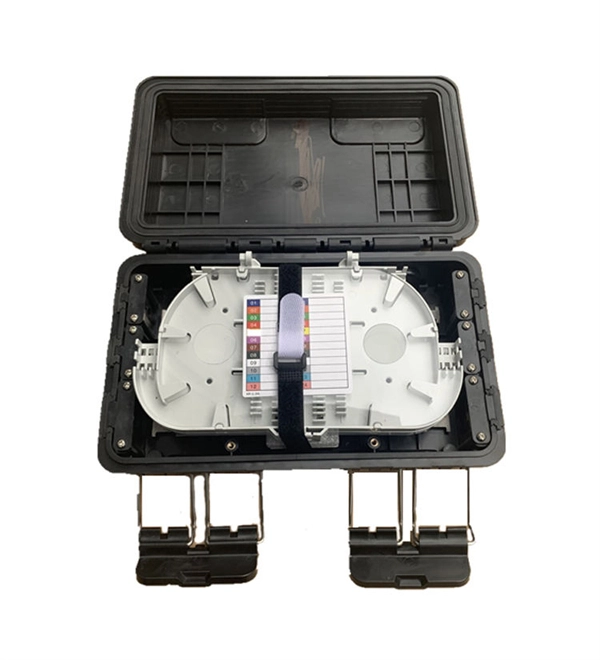
To confirm a cold solder joint, you can use a multimeter to test continuity. A cold solder joint forms when the solder does not properly bond the component lead to the pad—typically due to inadequate heat, oxidation, or poor technique. Generally, its appearance is smooth and bright. This guide explains what a cold solder joint is, what it looks like, why it happens, and how to reliably identify, fix, and prevent it. Whether you're troubleshooting a failed board or optimizing an SMT production line, this article gives you a practical, engineering-level reference for eliminating. Ultrasonic Pulse Velocity (UPV) is an effective non-destructive testing (NDT) method for quality control of concrete materials, and evaluating concrete integrity on or around the cold joint.
Usually the voltage is changed in increments of the rated voltage – typically 2. 5% for distribution (22/11 kV to 400 volt) transformers but finer, say 1. It explains how higher voltage reduces current, minimizes losses, and enables smaller, more cost-effective conductors, and outlines standard voltage levels for. It can be demonstrated that maintaining a high quality of voltage control will result in a higher level of permissible loading on feeders, and will defer investment for rebuilding or adding capacity. There are three main methods used to control the voltage at the end of a distribution feeder – By using control equipment to vary the voltage at the supply end of the feeder or at the load end and by controlling the current in the line by changing the power factor. They can correct voltage, but they have no effect on power factor. By Turn2Engineering Editorial Team Updated May 12, 2026 16 min read Core idea: Voltage regulation measures how well.
[PDF Version]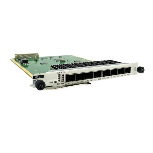
It is currently used in modern three-CCD cameras. An optically similar system is used in reverse as a beam-combiner in three- LCD projectors, in which light from three separate monochrome LCD displays is combined into a single full-color image for projection.OverviewA beam splitter or beamsplitter is an that splits a beam of into a transmitted and a reflected beam. It is a crucial part of many optical experimental and measurement systems, such as In its most common form, a cube, a beam splitter is made from two triangular glass which are glued together at their base using polyester,, or urethane-based adhesives. (Before these synthetic,. Beam splitters are sometimes used to recombine beams of light, as in a. In this case there are two incoming beams, and potentially two outgoing beams. But the amplitudes.
Contact us for competitive quotes on any of our power communication and smart grid products
Get a Quote