
Protective relays are commonly referred to by standard device numbers. In the design of electrical power systems, the ANSI Standard Device Numbers denote what features a protective device supports (such as a relay or circuit breaker). These types of devices protect electrical systems and components from damage when an unwanted event occurs, such as an electrical. The protection and control devices in electrical equipment can be referred to by numbers, with appropriate suffix letters when necessary, according to the functions they perform. The device numbers are enumerated in ANSI / IEEE Standard C37.

Another fundamental method is L–I–V characterization, where the optical output power (L) and voltage (V) are measured against the drive current (I) to determine key parameters like threshold current and slope efficiency. It is often necessary to quantitatively assess the quality, performance, and characteristics of laser diodes. Once known, the next set of choices revolves around mounting a laser diode and choosing the appropriate drivers, regulators, and choosing the placement of the diode within the lab.
Protection relays can be grouped by input, operating principle, and performance characteristics. Electro‑mechanical: Uses electromagnetic forces and moving parts. In this guide, we'll explore what protection relays are, how they're classified, the types. Protective Relay Definition: A protective relay is an automatic device that senses abnormal conditions in electrical circuits and triggers actions to isolate faults. They are intended to quickly identify a fault and isolate it so the balance of the system continue to run under normal conditions.
This guide provides a comprehensive overview of various transformer protection schemes and offers recommendations for relay selection, coordination, and settings. Another important standard is the IEC 61850, which focuses on communication protocols for substation automation systems. Table 1 – Transformer fault types/protection methods 1. In HV (High Voltage) and MV (Medium Voltage) substations, relay protection safeguards critical assets such as transformers, circuit breakers, and lines. • If current penetrates the limits of the thermal damage curve, insulation damage may occur.

Refocus optics by changing z-height (focus on lines) Decide which A-line, overlaps which B-line Is A up or down relative to B ? Switch OFF pickup tool vacuum before pickup Touchdown tool onto scale A- switch ON vacuum. Raise arm with scale A Check alignment is as before – perfectly. The OS-8171 Beam Splitter is designed to be used with the OS-8170 Brewster's Angle Accessory and the OS-8539 Educational Spectrophotometer System. ) In the Brewster's Angle experiment, the Beam Splitter is used with a. A beam splitter or beamsplitter is an optical device that splits a beam of light into a transmitted and a reflected beam. It is a crucial part of many optical experimental and measurement systems, such as interferometers, also finding widespread application in fibre optic telecommunications. In its. These versatile devices split an incident light beam into two or more separate beams, each with specific optical properties. One beam is typically reflected while the other is transmitted. Similar performance across a range of angle of incidence. I have been looking and either I can't find what I am looking for, or I just get.
[PDF Version]
The number of racks in a data center varies widely depending on its size and purpose, ranging from a handful in small server rooms to tens of thousands in hyperscale facilities. In short, it's highly variable. Why does it matter? Prevents wasted space, reduces hot spots, ensures compliance, and avoids costly retrofits. A typical enterprise data center might house hundreds of racks, while a large colocation facility could contain. When thinking about data centers, a common question is: how many servers fit inside these facilities? The answer depends on factors like size, design, and purpose. This calculator helps you plan rack layouts by calculating the total rack units.
Push a length of UF (underground feed) electrical cable into the conduit, then feed the end of the cable through the hole in the wall. Pull the cable all the way to the main electrical panel. In this video, we'll walk you through the process of wiring a home distribution box with a detailed connection diagram. If needed, rent a gas-powered trenching machine to reduce the amount of manual labor needed. It is mainly used to isolate fault circuits, prevent overload, and ensure the safe operation of. Buried conduits and ducts: Which conduits and ducts offer equivalent mechanical protection to armoured cables when buried in the ground? By: Michael Peace CEng MIET MCIBSE The use of unarmoured cables, such as HO7RN-F rubber flexible cables or unarmoured XLPE cables buried in the ground, is. cify the duct bank to be used. All primary cable installations and feeders larger than No. Any. The in-ground installation for CANTEX PVC junction boxes is also simple, but always be sure to follow all national and regional electrical codes when installing any electrical junction box.
[PDF Version]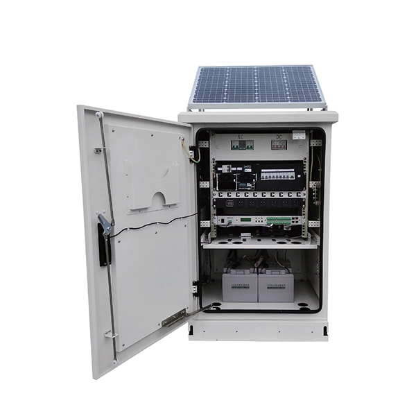
A typical full-size rack is 42U, which means it holds just over 6 feet (180 cm) of equipment, and a typical "half-height" rack is 18U–22U, which is around 3 feet (91 cm) high. The mounting-hole distance (as shown to the right) differs for 19-inch racks and 23-inch racks: 19-inch racks use uneven spacings (as shown to the right) while 23-inch.
Contact us for competitive quotes on any of our power communication and smart grid products
Get a Quote