
You can learn to connect and program a laser diode with Arduino in this tutorial. A laser diode makes a narrow beam of light. This is helpful for finding objects or lining things up in electronics projects. The steps in this tutorial are simple, so beginners can do them. Safety is. A laser diode is a cool component that you can do a lot of fun stuff with, from engraving wood to creating a light show or giving your robot eyes! They range from super cheap (or even free if you can find one in an old CD player!) to more expensive. When electric current flows through the p-n junction, the gain is. Laser Diode Module Tutorial: Description: This 100mW laser module emits a small intense focused beam of visible red light.
In summary, high reflectance in fibre optic networks can result from various causes, such as connector issues, bad splices, or dirty fibre ends. But with the help of an OTDR, you can pinpoint the problem areas and take action to fix them. Understanding the potential causes can help you solve the issue quickly and get your network up and running again. What is High. Fiber optic networks are celebrated for their speed and reliability, but even the best systems can encounter problems. This guide will walk you through diagnosing and resolving common. This guide dives deep into the most prevalent fiber optic network problems, their root causes, and actionable solutions. Or it could be caused by the quality of the connector itself, such as poor end-face geometry that doesn't pass the. Within the fiber link, microbends, macrobends, or breaks along the fiber can cause disruptions. Too many connections in a channel can push signal loss.
[PDF Version]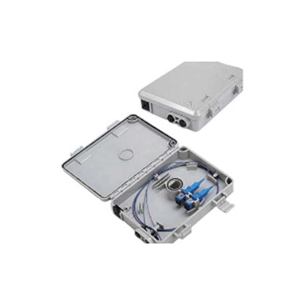
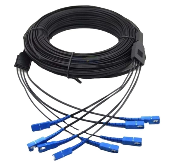
In September 2012, NTT Japan demonstrated a single fiber cable that was able to transfer 1 per second (10 bits/s) over a distance of 50 kilometers. Although larger cables are available, the highest strand-count single-mode fiber cable commonly manufactured is the 864-count, consisting of 36 ribbons each containing 24 strands of fiber. These high fiber count cables are used in, and as distribution cables in and networks.
Think of as-built drawings as the “Google Maps” of your network infrastructure. Without them, technicians and engineers are essentially guessing. The as-built drawing contains information on the actual implemented fiber route, including manhole locations, distances, terrain details, site coordinates, and landmarks. Field conditions, subsurface utilities, topography problems, and. This guide breaks down the seven categories of as-built artifacts every modern FTTH project requires, the file formats and accuracy standards customers expect, and the field workflow that lets a single crew capture everything in real time. They provide a detailed record of the actual construction and installation of telecom infrastructure, ensuring accuracy and facilitating future maintenance and upgrades1.
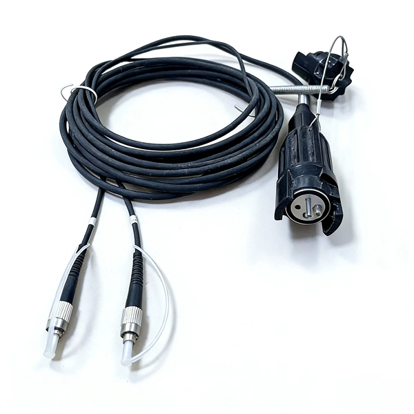
As the air pressure builds up, the jetting motion pushes the cable through the conduit. This will reduce the compressed air that pushes the cable through the. Minimize mechanical pressure on the outer sheath at crossing points: (armoured) cables crossing each other generate points of high pressure, so it is important when laying in figure 8 loops it is done in a correct way. When laying loops of fiber on a surface during a pull, use “figure-8” loops to. Some key considerations for installing optical fiber cable are highlighted below. Proper industry. stallers should consider bend radius, tension, jamming, and fill ratio before performing any conduit pull. Corning Optical Communications recommends the American Polywater® PULL-PLANNE able in conduit, observe the manufacturer's recommendations for maximum pulling tension and bend radius. Generally, 5m-10m should be reserved at the equipment end, and it should be appropriately extended if there are special requirements.
[PDF Version]
We look at how to install a consumer unit like a professional electrician, covering everything from circuit labelling, cable management, wiring, and safety checks. This step-by-step installation tutorial ensures you understand key considerations for domestic. Your digital dash install guide starts here: Installing a modern digital instrument cluster (e., 7-inch TFT or configurable LCD dash) is not a simple plug-and-play swap—even with OEM-compatible units. Use this guide to find out how to replace a thermostat and the tools you'll need for the job. The harness contains pins for various I/Os.
Another fundamental method is L–I–V characterization, where the optical output power (L) and voltage (V) are measured against the drive current (I) to determine key parameters like threshold current and slope efficiency. It is often necessary to quantitatively assess the quality, performance, and characteristics of laser diodes. Once known, the next set of choices revolves around mounting a laser diode and choosing the appropriate drivers, regulators, and choosing the placement of the diode within the lab.
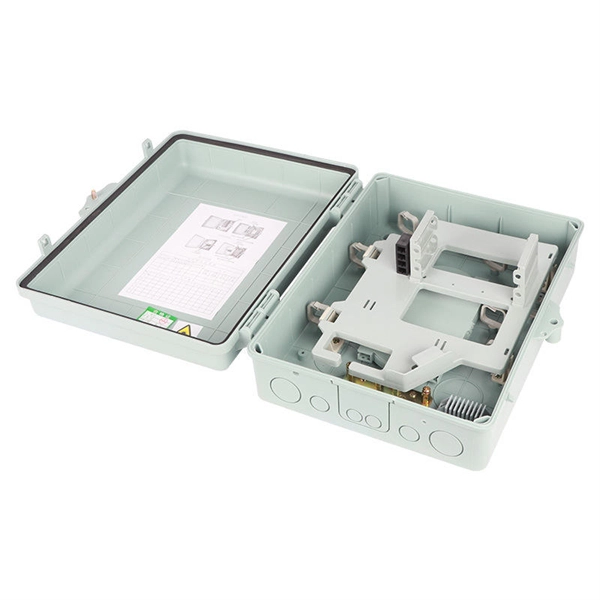
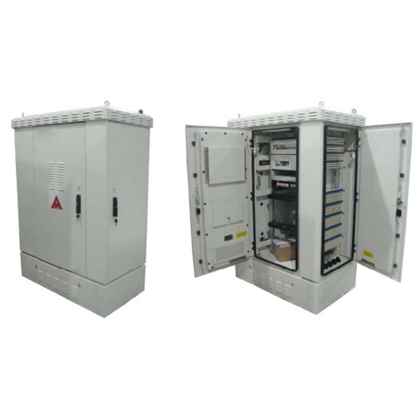
A electrical distribution box acts as the central hub for managing electrical power, directing the main supply into subsidiary circuits equipped with protective devices like circuit breakers or fuses. Bus bars within distribute electricity evenly, reducing energy loss and increasing. The distribution box (DB box) helps safely and efficiently distribute electrical power. Today, electrical systems are essential for homes and industries. Without it, managing power would be messy, unsafe, and inefficient.
A complete fiber optic cable production line in 2025 requires an initial investment of $750,000 to $2,500,000. With strong market demand, most businesses achieve a full return on investment (ROI). The cost of setting up and operating an optical fiber cable manufacturing unit can vary significantly based on several factors. Understanding these elements is critical to developing a competitive strategy and estimating potential returns on investment. In this article, we'll break down the key. The fiber optic cable market is primarily driven by the significant expansion of broadband infrastructure, along with rising investments in 5G networks, the increasing deployment of data centers, and a growing demand for high-speed communication across telecom, enterprise, and smart city projects. From investment breakdowns and technical specifications to operational expenses and geographic cost considerations, you'll gain actionable insights into what it takes to step into. The report presents a comprehensive capital cost analysis, detailing the financial investment required for setting up a fiber optic cable plant.
[PDF Version]
To perform an OTDR test correctly, you must: 1. Set core parameters (Wavelength, Distance, Pulse Width); 4. Run the test (Real-time or Average); 5. OTDR (Optical Time Domain Reflectometer) is a commonly used test equipment in fiber optic communications, which can help detect the loss, fault points and other performance indicators of fiber optic lines. For fiber optic engineers and technicians, mastering the use of OTDR Tester is the key to. In this video, we provide a step-by-step guide on how to operate an OTDR (Optical Time-Domain Reflectometer) for accurate fiber optic testing. more In this. OTDR settings are a balance between dynamic range, acquisition time, spatial resolution and accuracy.
Contact us for competitive quotes on any of our power communication and smart grid products
Get a Quote