
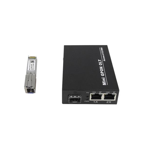
Q: How can receiver sensitivity be optimized? A: Receiver sensitivity can be optimized by employing techniques such as noise reduction, amplification, and signal processing, as well as careful detector selection and amplifier design. Optimizing SNR is all about tipping the balance in favor of the signal you want, so noise doesn't drown it out. That's the key to reliable communication and measurement. In essence, it measures how well a receiver can detect weak optical signals. amplitude shift keying (ASK) or on off keying (OOK). Voltage level is switched between two values, which are usually on and off.
Refocus optics by changing z-height (focus on lines) Decide which A-line, overlaps which B-line Is A up or down relative to B ? Switch OFF pickup tool vacuum before pickup Touchdown tool onto scale A- switch ON vacuum. Raise arm with scale A Check alignment is as before – perfectly. The OS-8171 Beam Splitter is designed to be used with the OS-8170 Brewster's Angle Accessory and the OS-8539 Educational Spectrophotometer System. ) In the Brewster's Angle experiment, the Beam Splitter is used with a. A beam splitter or beamsplitter is an optical device that splits a beam of light into a transmitted and a reflected beam. It is a crucial part of many optical experimental and measurement systems, such as interferometers, also finding widespread application in fibre optic telecommunications. In its. These versatile devices split an incident light beam into two or more separate beams, each with specific optical properties. One beam is typically reflected while the other is transmitted. Similar performance across a range of angle of incidence. I have been looking and either I can't find what I am looking for, or I just get.
[PDF Version]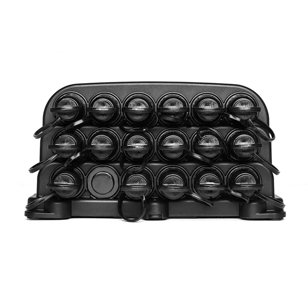
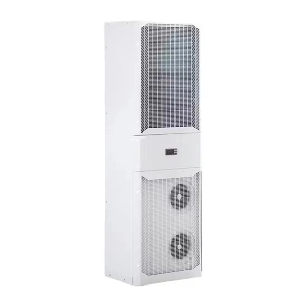
To configure network settings, enter the appropriate “net” command and press Enter. All commands are case sensitive. Section 1 – System Overview Intelligent Network Controller The Panduit G5 Intelligent PDUs have an integral, hot swappable Intelligent Network Controller. The Intelligent Network Controller contains an OLED display, control buttons, USB Interface, Serial and Sensor ports, and a recessed Reset. Connecting the PDU to a LAN provides communication through an Internet or Intranet connection. You can monitor the PDU from any computer connected to the same network. The PDU is set to use DHCP (Dynamic Host Configuration Protocol) by default when delivered. If IP is successfully assigned, you. There are two ways to connect new PDUs to a network: using an individual IP address for each PDU, connecting directly to a network switch, or connecting through Conteg Spain's redundant network cascading architecture. SOLUTION: Conteg Spain PDUs can cascade 16 PDUs using a single IP address. The GeistTM Rack Power Distribution Unit (rPDU) gives data center managers the flexibility to install the intelligence required today, with the option to upgrade technology as needs evolve.
[PDF Version]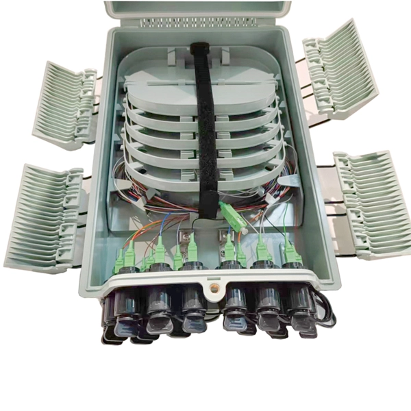
Start adjusting the fiber coupler by turning the three positioning screws one after the other up to half a turn in each direction, until the power meter detects a signal. How measured fiber parameters help to choose the best coupling and collimation optics. A stable measurement setup is fundamental for any successful measurement. A major cause of frustration and error is the need to continuously readjust optomechanical equipment because of continuous instabilities. This tab provides a brief explanation of how we determine several key specifications for our 1x2 couplers. Polarization-maintaining single- mode fibers (PM fibers) are rotation-ally non-symmetric. When using fiber optics, one often needs to use fiber couplers for various purposes. Directional 2 × 2 couplers (see Figure 1) are usually used for. The T F D is a compact, rugged fiber coupler designed to be easy to use, while still having all OPTICA IBER OCK the required degrees of freedom to allow maximum coupling efficiency to be achieved. These specialized devices enable controlled light splitting while preserving polarization states, a critical requirement in numerous.
[PDF Version]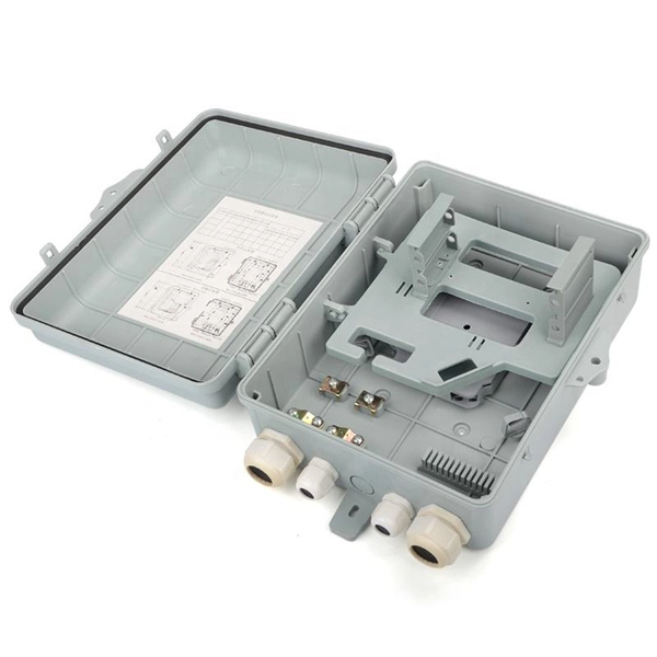
Observe the readings on the fiber meter as you turn the adjustment knob on the fiber cable counter-clockwise. Adjust the knob until your desired dBm level is reached. Post-installation, perform an initial test with an optical power meter to gauge the optical power at both ends of the attenuator. Document these values for. Adjusting the Attenuation Value Fine-tune the attenuation value in accordance with the system's specific requirements. Attenuation stability Excellent return loss characteristics Easy installation & well packaged Telcordia.
To set photoelectric sensor values effectively, start by installing the sensor according to the manufacturer's guidelines, ensuring proper alignment and clean lenses. Power on the system and access the settings via a push-button interface or software tool. 1 Energy sensors are based on the pyroelectric effect. 1 Safety 1 General Information The PM100D Handheld Optical Power and Energy Meter is designed to measure the optical power of laser light or other monochromatic or near monochromatic light sources and the energy of pulsed light sources. By following these steps, you can optimize the sensor's performance for your specific application, ensuring accurate and. This manual contains 'WARNINGS” and 'ATTENTION” labels in this form, to indicate danger for persons or possible damage to equip-ment. more An optical power meter should be configured specifically for the light incident on the power sensor.
[PDF Version]
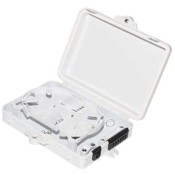
Attach a ground wire from one of the threaded studs (A) at the bottom of the housing, to the mounting plate (B). The ground resistance between all system parts shall be < 0. This position is the connection point of the grounding wire in the. Power from factory ground must be installed by a qualified electrician. Each DISTRIBUTION BOX and controller must be grounded. When inspecting the interior of a stainless steel outdoor electrical box distribution box, pay attention to the copper or tin-plated terminals on the base plate or side walls. Make sure all tools are intact to prevent accidents during the grounding.
Contact us for competitive quotes on any of our power communication and smart grid products
Get a Quote