
This guide provides a step-by-step approach to relay circuit troubleshooting, covering everything from identifying relay failure analysis to relay coil testing and addressing relay contact problems. Let's dive into the details to help you diagnose and fix issues with precision and efficiency. The Voltage Protection Circuit described below cuts out power to the load if the input voltage is too high or too low. The voltage at which the power is cut off can be adjusted. What is an Over Voltage Relay? What is an Undervoltage Relay? When the voltage and time values cross, a tripping signal is sent to circuit breaker. Before you can fix low voltage, it's important to understand what's causing it. Some of the most common reasons include: Overloaded circuits – Too many appliances or devices running at once can cause voltage drops. more Sound or visuals were significantly. Protective relays and devices have been developed over 100 years ago to provide “lastline”of defense for the electrical systems.
[PDF Version]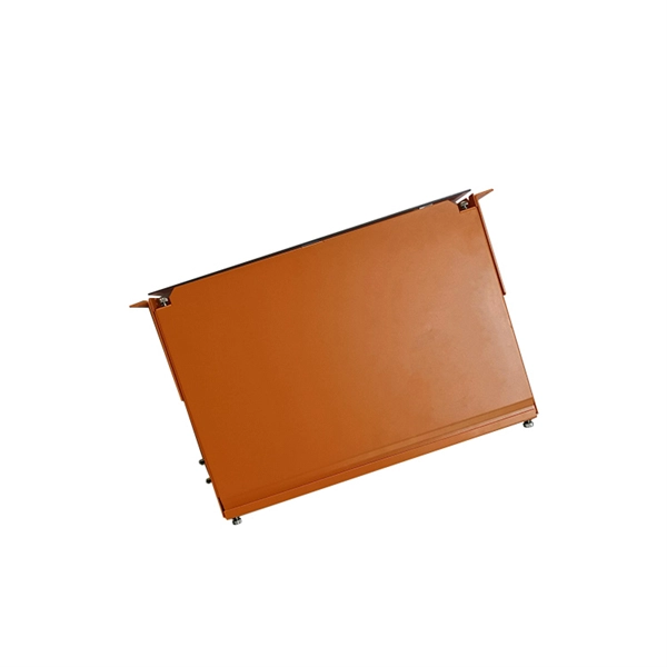
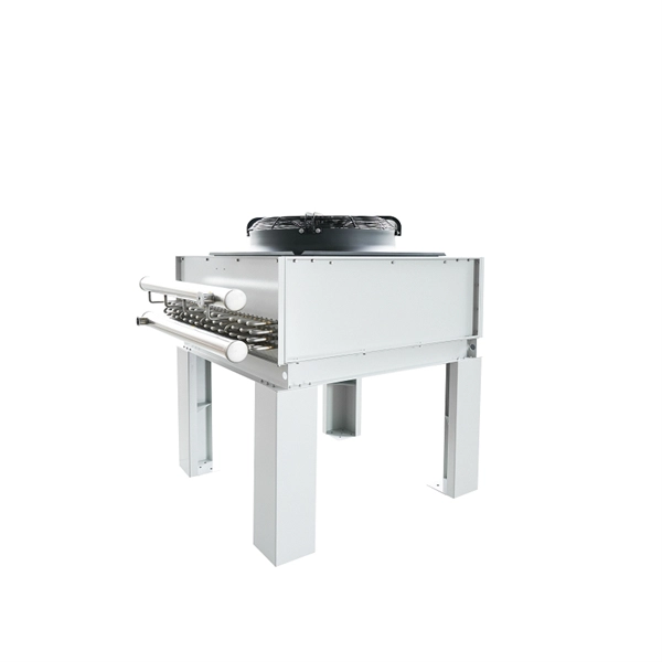
Usually the voltage is changed in increments of the rated voltage – typically 2. 5% for distribution (22/11 kV to 400 volt) transformers but finer, say 1. It explains how higher voltage reduces current, minimizes losses, and enables smaller, more cost-effective conductors, and outlines standard voltage levels for. It can be demonstrated that maintaining a high quality of voltage control will result in a higher level of permissible loading on feeders, and will defer investment for rebuilding or adding capacity. There are three main methods used to control the voltage at the end of a distribution feeder – By using control equipment to vary the voltage at the supply end of the feeder or at the load end and by controlling the current in the line by changing the power factor. They can correct voltage, but they have no effect on power factor. By Turn2Engineering Editorial Team Updated May 12, 2026 16 min read Core idea: Voltage regulation measures how well.
[PDF Version]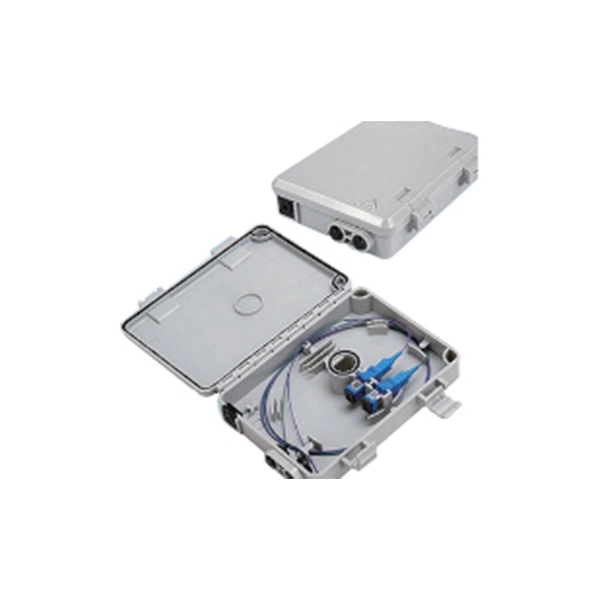
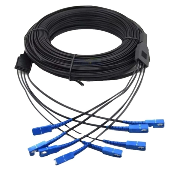
In September 2012, NTT Japan demonstrated a single fiber cable that was able to transfer 1 per second (10 bits/s) over a distance of 50 kilometers. Although larger cables are available, the highest strand-count single-mode fiber cable commonly manufactured is the 864-count, consisting of 36 ribbons each containing 24 strands of fiber. These high fiber count cables are used in, and as distribution cables in and networks.
The distribution box is divided into power distribution box and lighting distribution box, which is the last level equipment of the distribution system. It helps control and distribute electricity to different areas. Inside, you'll find parts like circuit breakers and fuses that protect the system from problems like overloads and short circuits. From powering homes and industrial facilities to supporting medium-voltage infrastructure, these enclosures ensure safe, efficient, and reliable power distribution. This guarantees the safe flow of electricity, improves reliability, simplifies maintenance, and also helps to comply with electrical standards for the distribution.
Think of as-built drawings as the “Google Maps” of your network infrastructure. Without them, technicians and engineers are essentially guessing. The as-built drawing contains information on the actual implemented fiber route, including manhole locations, distances, terrain details, site coordinates, and landmarks. Field conditions, subsurface utilities, topography problems, and. This guide breaks down the seven categories of as-built artifacts every modern FTTH project requires, the file formats and accuracy standards customers expect, and the field workflow that lets a single crew capture everything in real time. They provide a detailed record of the actual construction and installation of telecom infrastructure, ensuring accuracy and facilitating future maintenance and upgrades1.
Contact us for competitive quotes on any of our power communication and smart grid products
Get a Quote