
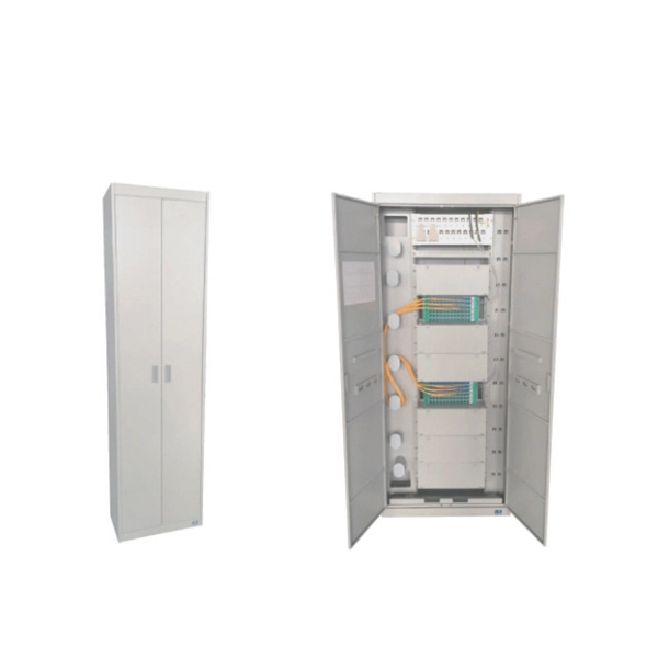
Our splice boxes are used to securely connect and distribute fibre optic cables by protecting spliced glass fibres from external influences. Price and other details may vary based on product size and color. The front panel is provided with additional holes to fix the adapter with screws. The cover h Faber fibre splice boxes are telescopic. AFL offers robust fiber optic splice closures—including Apex® high-density and LightGuard® weathertight and sealed models—for above-ground, aerial, and buried applications.
A main drawback is the complexity of testing and troubleshooting, as well as the need for detailed GIS records to accommodate splitter placement. Training can also be challenging for those unfamiliar with this architecture. Centralized splits typically use higher fiber count cables than distributed split networks, increasing both material and splicing labor costs. Another disadvantage is the aesthetic impact of the PON. A GPON splitter is a passive optical device that takes a single fiber input and splits it into multiple outputs, typically in ratios like 1:2, 1:4, 1:8, 1:16, 1:32, and 1:64. The splitting process introduces signal attenuation, making placement strategy critical for network performance. PON, developed in the mid-1990s, was originally designed to allow internet service providers (ISPs) to deliver broadband triple-play services (data, voice, and video) to residential users. By dividing a single optical signal from a central Optical Line Terminal (OLT) into multiple outputs for Optical Network. Morgan said the downside is that there is “a little bit less ability to troubleshoot” because the terminals are not all in one place. “This is becoming more popular for.
[PDF Version]
The beam splitter splits and then recombines infrared radiation, while the detector picks up the resulting signal. It's sensitive to both intensity and frequency. Together, they decide just how accurately an instrument captures those unique infrared “fingerprints” from different. A beam splitter or beamsplitter is an optical device that splits a beam of light into a transmitted and a reflected beam. It is a crucial part of many optical experimental and measurement systems, such as interferometers, also finding widespread application in fibre optic telecommunications. In its. Thorlabs' Single Mode Fiber-Based Polarization Beam Combiners (PBC) or Splitters are designed to either combine two orthogonal polarizations into a single fiber or split a single input into its orthogonal linear polarizations through two fiber outputs. The device utilizes birefringence, which is the property of certain materials.
[PDF Version]
It is currently used in modern three-CCD cameras. An optically similar system is used in reverse as a beam-combiner in three- LCD projectors, in which light from three separate monochrome LCD displays is combined into a single full-color image for projection.OverviewA beam splitter or beamsplitter is an that splits a beam of into a transmitted and a reflected beam. It is a crucial part of many optical experimental and measurement systems, such as In its most common form, a cube, a beam splitter is made from two triangular glass which are glued together at their base using polyester,, or urethane-based adhesives. (Before these synthetic,. Beam splitters are sometimes used to recombine beams of light, as in a. In this case there are two incoming beams, and potentially two outgoing beams. But the amplitudes.
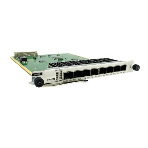
Testing a splitter or other passive fiber optic devices like switches is little different from testing a patchcord or cable plant using the two industry standard tests, OFSTP-14 for double-ended loss (connectors on both ends) or FOTP-171 for single-ended testing. A passive device used to split or combine signals on fiber optics may be called a splitter, combiner or coupler, but splitter is the most common term. 6inch color touch screen, button/touch dual operation; Internal integration of eight major functional modules, multi-functional. As fiber deployments become commonplace, network owners and technicians are paying more attention to the two crucial devices for testing fiber optical cables: the Optical Loss Test Set (OLTS) and the Optical Time Domain Reflectometer (OTDR). An OLTS provides the most accurate insertion loss. The CertiFiber® Pro Optical Loss Test Set (OLTS) can be used to check that the loss of a PON Splitter (often referred to in various standards as a non-wavelength-selective or wavelength-selective branching device) to check that it is within the allowed defined limits. To view the full specifications, download the spec sheet below.
[PDF Version]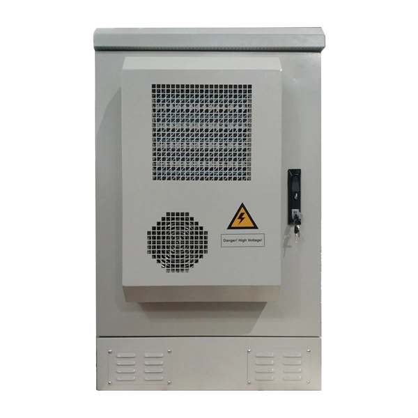
For beam splitters with two incoming beams, using a classical, lossless beam splitter with Ea and Eb each incident at one of the inputs, the two output fields Ec and Ed are linearly related to the inputs through where the 2×2 element is the beam-splitter transfer matrix and r and t are the and along a particular path through the beam splitter, that path being indicated by the subsc.
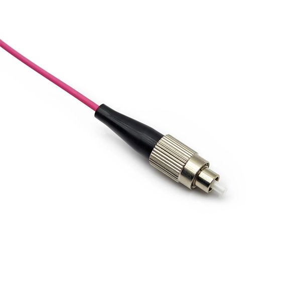
An FBT (Fused Biconical Taper) splitter is made by fusing and tapering two or more optical fibers. By changing the evanescent field coupling between the fibers (coupling degree, coupling length) and the fiber core radius, different branching ratios can be achieved. Developed in the 1980s, FBT splitters have evolved to support modern telecommunications demands, from fiber-to-the-home. A fiber-optic splitter, also known as a beam splitter, is based on a quartz substrate of an integrated waveguide optical power distribution device, similar to a coaxial cable transmission system. The optical network system uses an optical signal coupled to the branch distribution. Unlike active devices (which require power), splitters operate without electricity, relying solely on the physics of. At its core, an FBT splitter is a passive optical device that takes a single optical input signal and divides it into two or more output signals.
[PDF Version]Contact us for competitive quotes on any of our power communication and smart grid products
Get a Quote