
This article provides a comprehensive framework that governs various aspects of cable tray installations, including the types of cables that are deemed acceptable for use, requirements for grounding and bonding, and stipulations regarding tray fill capacity. Cable tray may be used as the Equipment Grounding Conductor (EGC) in any installation where qualified persons will service the installed cable tray system. Each method must be selected based on environment, standards, and system type. Grounding. Cable tray systems have become an essential component in the infrastructure of modern commercial buildings, smart offices, data centers, and various industrial facilities. These systems provide an efficient and adaptable solution for managing a wide range of cables, including power cables, control. Understanding cable‐tray e arthing comes early in the 18th-Edition module of the electrician courses at Elec Training Birmingham.
[PDF Version]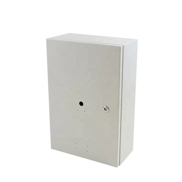
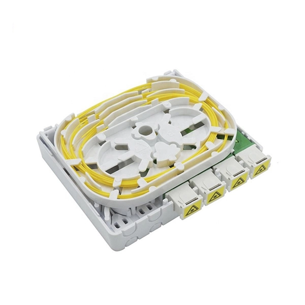
Attach a #6 AWG copper ground wire and ground lug together. In a line-up of more than one. Recommendation ITU-T L. 151 refers to the installation of optical fibre ground wire cable. It deals with the factors that should be considered in determining the characteristics of this type of cable, the apparatus that should be used, the precautions that should be taken in handling the reels, and. Power from factory ground must be installed by a qualified electrician. This position is the connection point of the grounding wire in the. Follow these steps at each cable entry point and termination location to achieve a compliant, safe ground bond: Identify metallic components. Strip back approximately 6–8 inches of the outer jacket using a cable slitter or ringing tool. Visually identify armor, strength members, or foil layers. The basic rule achieves this through an equipment grounding jumper; four exceptions.
[PDF Version]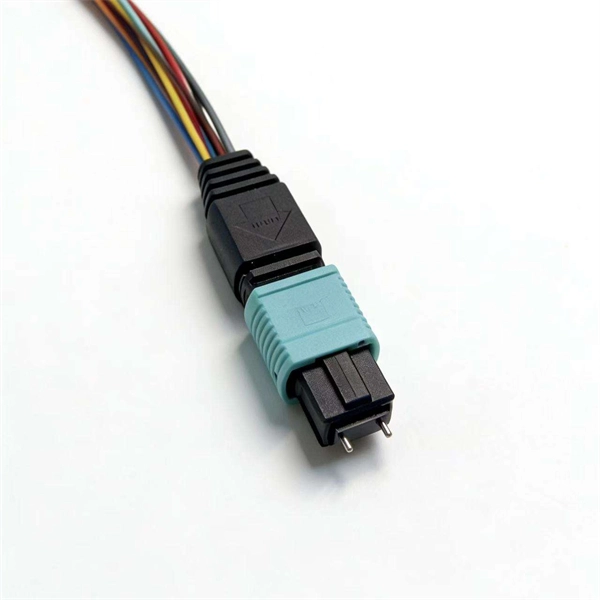
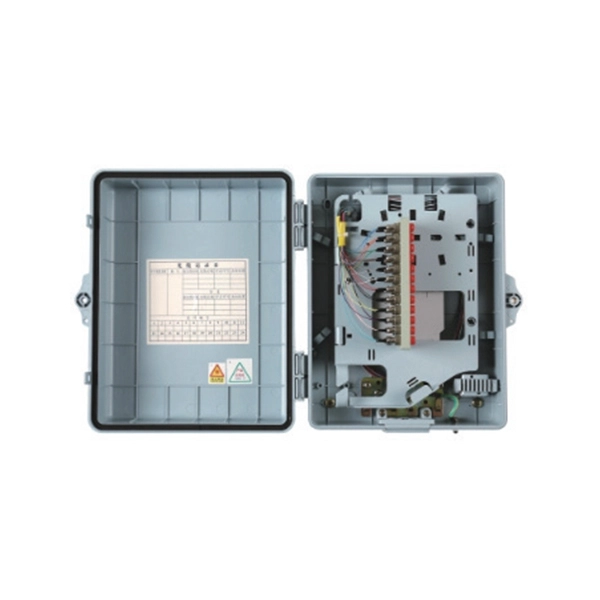
To check if a metal box is grounded using a multimeter: Set the multimeter to the resistance (ohms) setting. Visual Inspection: Begin by visually inspecting the metal box and its components. Knowing how to do this could prevent an electrical shock from happening. What Will Happen if You Have an Ungrounded Panel Box? To test your household ground, you need the following tools: In this procedure, preparing a. Today, we're diving deep into the world of distribution box grounding, breaking down the standards, and shining a light on those sneaky mistakes that even experienced electricians sometimes make.

Abstract—The paper presents a conceptual comparison of the inherent properties of the DC UPS and the AC UPS system solutions for uninterruptible operation of data centers and other critical and sensitive loads. Compared parameters are efficiency, reliability, power quality and. The uninterruptible power supply (UPS) for sensitive or safety-critical 24?V?DC systems supplied from the AC mains is particularly important in the event of blackouts, voltage fluctuations, or flicker. In an emergency, it is vital to avoid dangerous system failures, loss of productivity, or data. AC is characterized by a flow of electric charge that periodically reverses direction, while DC maintains a consistent flow in a single direction. In the context of UPS, these terms are associated with. ENERGY STORAGE Solutions Multiuse solutions (self-consumption optimisation, supply security, load optimisation) precisely tailored to your application, scalable, redundant and future-proof. In addition, we offer hybrid systems that seamlessly integrate AC and DC-powered components.
[PDF Version]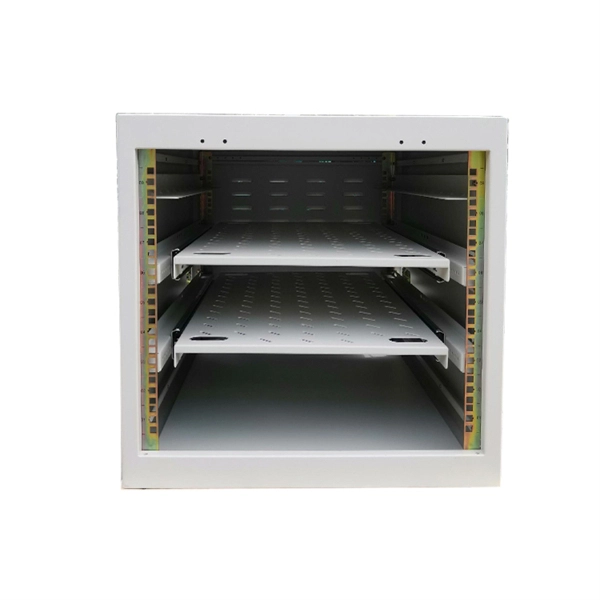
The grounding system provides a low-impedance path for fault current and limits the voltage rise on the normally non-current-carrying metallic components of the electrical distribution system. This helps to reduce the potential difference that exists between conductive parts and the earth. Equipment Protection: Grounding protects substation. Think of it this way: That distribution box in your facility? It's not just a metal container – it's the quarterback coordinating all electrical flows. If its grounding fails, every connected device becomes vulnerable. Each DISTRIBUTION BOX and controller must be grounded. 26 mm 2 (10 AWG) ground wire must be used, and in all other markets a 6 mm 2 must be used. During fault conditions, low impedance results in high fault current flow, causing overcurrent protective. This guide covers everything you need to know about safe grounding in industrial plants, including key threats, terminologies, and grounding systems. Why Grounding Is Essential Grounding is vital for two primary reasons: Personal Safety: Proper grounding ensures faults are quickly cleared by.
[PDF Version]
26 mm 2 (10 AWG) ground wire must be used, and in all other markets a 6 mm 2 must be used. **Connect the ground wire**: Connect one end of the insulated copper wire to the grounding grid and lead the other end into the distribution box and connect it to the ground bus bar of the distribution box. Connect electrical service boxes to grounding rods. Electrical wire is designed to conduct current from a. Grounding an electrical panel is an important step to keep your home and family safe. You'll learn. Power from factory ground must be installed by a qualified electrician.
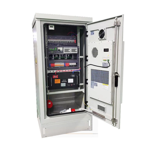
The busbar or vertical grounding strip should be used to provide a visually verifiable, all-copper grounding path. When equipment does not provide a lug-mounting pad, the next best option is to bond the equipment mounting flanges directly to the rack rails. A grounding busbar in a telecom cabinet is a conductive component used to connect all grounding points within the system. A poor layout can quietly undermine reliability and maintenance. In. To mount a bus bar to an assembly structure, hardware (studs, holes, etc. ) can be manufactured into the conductors. Mersen offers in-house conductor plating in tin. Busbar design in switchgear ensures safe, reliable power distribution by balancing current capacity, thermal performance, mechanical strength, insulation, and standards compliance.
Grounding electrode conductor (GEC) – wire connecting the panel to the ground rod. Drive a ground rod into the earth near the panel. Connect the GEC securely to the. This guide will walk you through the process of installing a grounding bar in a Siemens panel, ensuring code compliance and safety. Preparation Safety is paramount. Key steps include driving a ground rod deep into the soil, attaching the grounding wire, connecting it to the panel's grounding. First, panels must have a way to ground all metal components that could be contacted by a person (pretty much all of them). It's the central hub designed to safely channel dangerous fault currents away from your equipment and, more importantly, away from your personnel. You'll learn what tools you need, how to do the job safely, and how to check if everything is working properly.
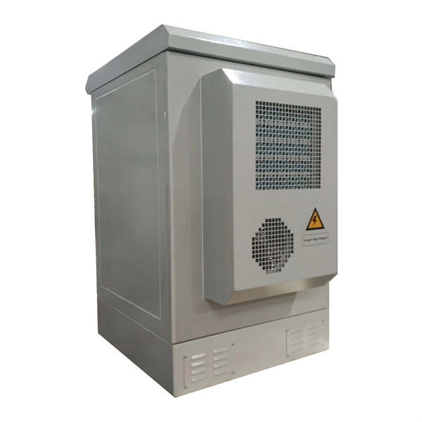
Attach a ground wire from one of the threaded studs (A) at the bottom of the housing, to the mounting plate (B). The ground resistance between all system parts shall be <. Power from factory ground must be installed by a qualified electrician. Each DISTRIBUTION BOX and controller must be grounded. 26 mm 2 (10 AWG) ground wire must be used, and in all other markets a 6 mm 2 must be used. The International Electrotechnical Commission (IEC) has developed standards. Electrical grounding is a fundamental safety measure designed to protect people and property from electrical faults. Any engineer dealing with power supply networks needs to understand the basic.
In order to ensure electrical safety in the railway network, grounding must be installed on all metal parts of structures and devices users can come into contact with. The resistance of grounding must not excee.
Contact us for competitive quotes on any of our power communication and smart grid products
Get a Quote