
A distribution box uses MCBs, RCDs, and busbars to protect circuits, prevent shocks, and ensure safe power distribution in homes and buildings. You use a distribution box to divide electrical power into smaller circuits. Whether it's a home, office, or factory. For procurement professionals, electrical contractors, and project managers, choosing the right Distribution Box (DB Box) is a critical decision that directly impacts system safety, reliability, and long-term operating costs. Residual Current Circuit Breaker (RCCB): RCCBs detect small imbalances in.
The main parts are the Miniature Circuit Breaker (MCB), Residual Current Device (RCD), busbars, and the main switch. Safe habits and checking the box often help stop electrical accidents. It acts as a protective enclosure that houses several key components, such as circuit breakers, fuses, and bus bars. We offer bespoke, custom-made terminal boxes and terminal box combinations, as well as standard products with short delivery times. Our products are certified for installation technologies all over the. A distribution board (also known as panelboard, circuit breaker panel, breaker panel, circuit breaker, electric panel, fuse box or DB box) is a component of an electricity supply system that divides an electrical power feed into subsidiary circuits while providing a protective fuse or circuit. The distribution board, consisting of several electrical components, can be described as a panel that supplies electricity to various electrical appliances. In this comprehensive guide, we will explore.
[PDF Version]
A distribution box uses MCBs, RCDs, and busbars to protect circuits, prevent shocks, and ensure safe power distribution in homes and buildings. You use a distribution box to divide electrical power into smaller circuits. This guide primarily analyzes structural engineering characteristics, technical specifications, and actual installation procedures to achieve optimal field performance. Inside, you'll find parts like circuit breakers and fuses that protect the system from problems like overloads and short circuits. We also highlight how reliable manufacturers like NUOMAK support stable, compliant, and cost-effective power distribution.
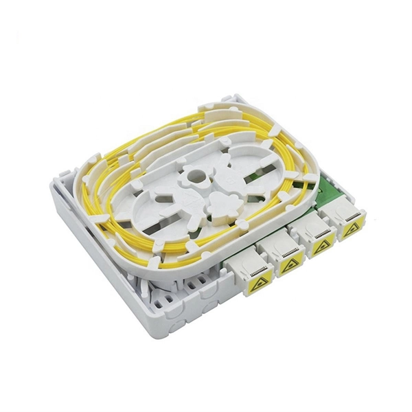
Standard high-performance fiber optic data cables do not contain copper elements. These components help ensure compatibility with networking hardware and enable secure connections between fiber optic devices. Fiber optic cables have revolutionized data transmission. ■ The Five Key Parts of a Fiber Optic Cable A fiber optic cable is composed of five core elements: Every hardware component has a specific function for proper signal transfer, construction resilience, and environmental defense. To discuss the way forward, we need to understand them one by one.

It performs the electro-optical conversion and includes components such as the laser, MPD, TEC, isolator, Mux, and coupling lens. It comes in various packaging forms like TO-CAN, Gold-BOX, COC (chip on chip), and COB (chip on board). As an important part of the optical fiber communication system, the optical module plays the role of photoelectric conversion. CDR not only ensures signal integrity and stability but also plays a pivotal role in. Optical modules are devices used to connect network devices, transmit and receive data between network devices, and can be used to convert optical and electrical signals. This article will introduce you to the. What are the Internal Components of an Optical Module? Expert in access network, PON, GPON, etc. IC Reference Search for certified products (Crystal Devices) by manufacturer name.
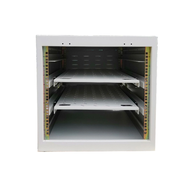
This article provides a comprehensive framework that governs various aspects of cable tray installations, including the types of cables that are deemed acceptable for use, requirements for grounding and bonding, and stipulations regarding tray fill capacity. Cable tray may be used as the Equipment Grounding Conductor (EGC) in any installation where qualified persons will service the installed cable tray system. Each method must be selected based on environment, standards, and system type. Grounding. Cable tray systems have become an essential component in the infrastructure of modern commercial buildings, smart offices, data centers, and various industrial facilities. These systems provide an efficient and adaptable solution for managing a wide range of cables, including power cables, control. Understanding cable‐tray e arthing comes early in the 18th-Edition module of the electrician courses at Elec Training Birmingham.
[PDF Version]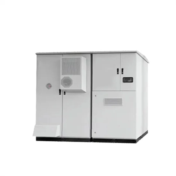
Grounding and bonding are mandatory for metallic trays. Tray fill limits must be calculated properly. Mesh trays reduce installation time while supporting compliance. 60(A) “Metal Area Requirements for Cable Trays used as Equipment Grounding Conductors” shows the minimum cross-sectional area of cable tray side rails (total of both side rails) required for the cable tray to be used as the Equipment Grounding Conductor (EGC) for a specific Fuse Rating. Table 392. Understanding NEC Article 392: Cable. The intent of this article is to review grounding practices for cable tray wiring systems. A rung spacing of 6 to 9 inches (150 to 230 mm) is preferable when the cable tray cont d for instrumentation and control applications that require.
The grounding system provides a low-impedance path for fault current and limits the voltage rise on the normally non-current-carrying metallic components of the electrical distribution system. This helps to reduce the potential difference that exists between conductive parts and the earth. Equipment Protection: Grounding protects substation. Think of it this way: That distribution box in your facility? It's not just a metal container – it's the quarterback coordinating all electrical flows. If its grounding fails, every connected device becomes vulnerable. Each DISTRIBUTION BOX and controller must be grounded. 26 mm 2 (10 AWG) ground wire must be used, and in all other markets a 6 mm 2 must be used. During fault conditions, low impedance results in high fault current flow, causing overcurrent protective. This guide covers everything you need to know about safe grounding in industrial plants, including key threats, terminologies, and grounding systems. Why Grounding Is Essential Grounding is vital for two primary reasons: Personal Safety: Proper grounding ensures faults are quickly cleared by.
[PDF Version]Contact us for competitive quotes on any of our power communication and smart grid products
Get a Quote