
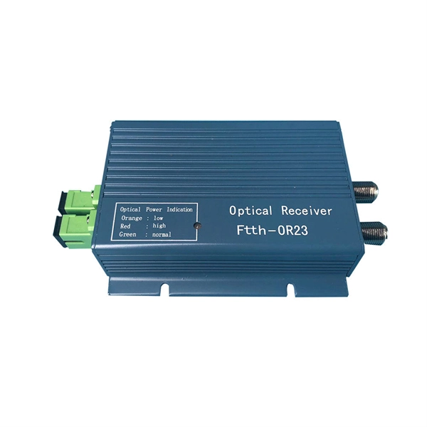
Optical testing involves measuring the laser diode's output power, wavelength, spectrum, and beam profile. These parameters are critical for laser diode applications that require precise and stable optical performance, such as fiber-optic communication systems and optical sensors. 📦 For purchasing, use the RP Photonics Buyer's Guide for laser diode testing. What is Laser Diode Testing? Why is laser. The light-current-voltage (L-I-V) sweep test is a fundamental measurement that determines the operating characteristics of a laser diode (LD). The versatile LIV Test System combines source and measurement. This comprehensive guide dives deep into the methods and considerations involved in testing laser diodes using a multimeter, providing practical insights and actionable steps for ensuring accurate results and preventing costly errors.
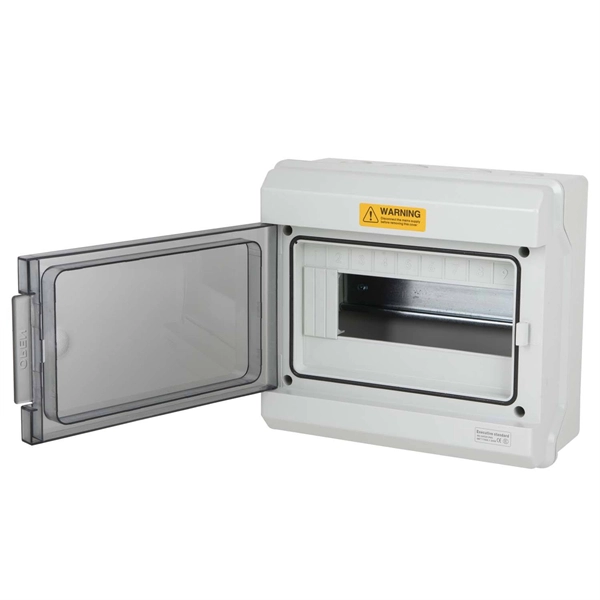
Attach a ground wire from one of the threaded studs (A) at the bottom of the housing, to the mounting plate (B). The ground resistance between all system parts shall be < 0. There are several factors that make substation grounding absolutely necessary. Knowledge of the various types of system grounding and performance characteristics is critical when designing or operating an electrical system. Then we. Where continuity of service is a high priority, high-resistance grounding can add the safety of a grounded system while minimizing the risk of service interruptions due to grounds. Each DISTRIBUTION BOX and controller must be grounded.
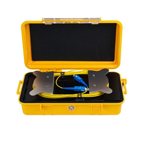
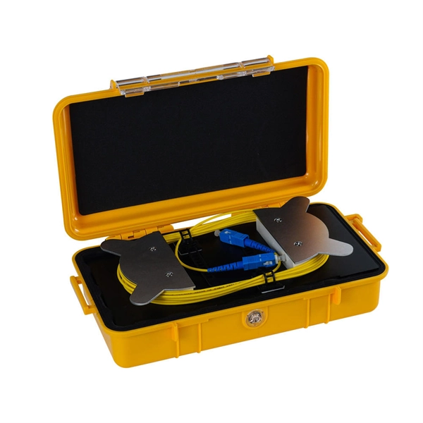
The tutorial in this section gives instructions on how to set up for a bi-directional SmartLoop test, set up the launch compensation function, make connections, do a test, and save the results. Splices are critical points in the optical fibre network, as they strongly affect not only the quality of the links, but also their lifetime. Not only does this cut the testing time by at least half, it also enables bi-directional. As the name implies, bidirectional OTDR testing is a method of optical fiber characterization and loss testing that is performed from both ends of the fiber run. The complexity of post-processing. Corning recommends that all fiber optic systems be tested to a minimum set. Optical Time Domain Reflectometers (OTDRs) play a crucial role in identifying and resolving these issues swiftly and accurately.
The loss value of a pigtail connector and its associated splice with matching mode field diameters should not exceed 0. Pigtail traces for all. at system. Corning recommends that all fiber optic systems be tested to a minimum set of standards. So, you drop everything and i vestigate. FOA standards align with IEC and TIA, giving you clear steps to earn trusted certification. No part of this book may be reproduced or utilized in any form or means, electronic or mechanical, including photocopying, recording, or by any information storage and retrieval system, without pe n optical fiber to a distant receiver. The electrical signal is. To be able to judge whether a fiber optic cable plant is good, one does a insertion loss test with a light source and power meter and compares that to an estimate of what is a reasonable loss for that cable plant.
Mounting Clamps: These are great for securing cable trays to walls or ceilings. Our focus has always been on solutions from the field of cable support systems. Establishing partnerships. This guide covers the critical steps, from selecting the right electrical cable tray and performing accurate cable fill calculations to managing a safe cable pull through and ensuring all bonding and grounding requirements are met. Cable ladder systems and cable tray systems shall be manufactured in accordance with BS EN 61537, channel support. association representing the major electrical equipment manufac-turers in the U. The Cable Tray ng standards, performance standards, test standards and application in this document have been tested extens ompetent professional en completely installed, without damage either to conductors or. Cable trays play a vital role in supporting electrical cables and wires in commercial, industrial, and utility installations. For proper installation, design, and maintenance, adherence to international standards is essential. The Ladder Tray features light, rugged, tubular steel construction.
[PDF Version]Contact us for competitive quotes on any of our power communication and smart grid products
Get a Quote