

Link aggregation (also known as port trunking or link bundling) combines multiple physical links into a single logical link. This increases bandwidth and provides redundancy. It's commonly used to connect aggregate switches to core switches or access switches. This arrangement increases throughput beyond what a single relationship could sustain, offers redundancy in case one of the links. It is a networking tool called an aggregation switch that enables the consolidation of several network connections into a single link.
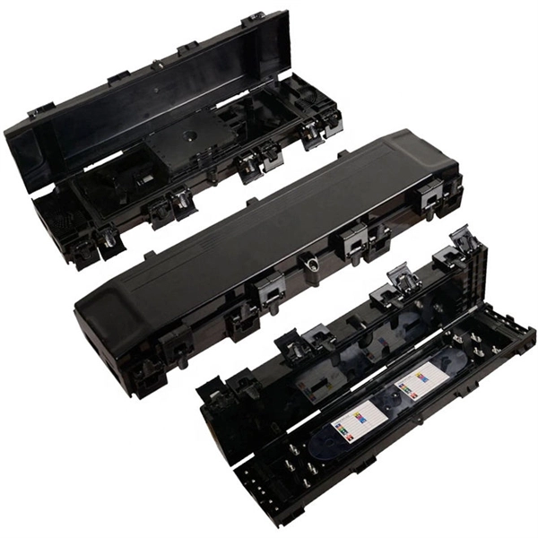
Check the electrical load and ensure that the sensors do not exceed the 10 Amp maximum. Adequate system designs allow for the system to withstand and isolate faults while not causing additional damage and/or outages. Do not touch live parts, turn off the corresponding power switch to avoid the risk of electric shock. Make sure the power supply is. However, the key to a safe and reliable system lies in proper installation. If it's done poorly, you risk short circuits, fire hazards, or system failure. In this guide, we'll break down everything you need to know to install. Outdoor low-voltage power distribution boxes (hereinafter referred to as "distribution boxes") are low-voltage distribution equipment used in 380/220V power supply systems to receive and distribute electrical energy.
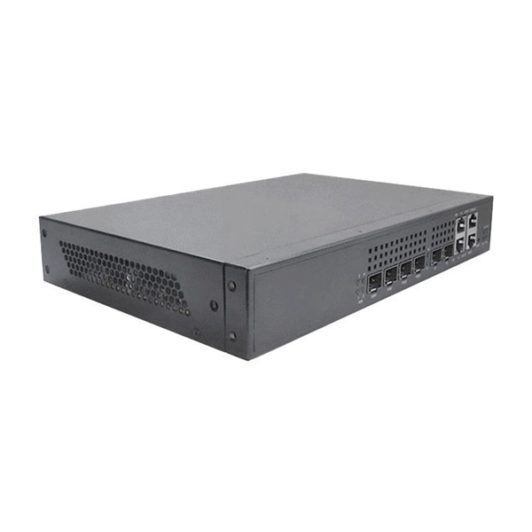
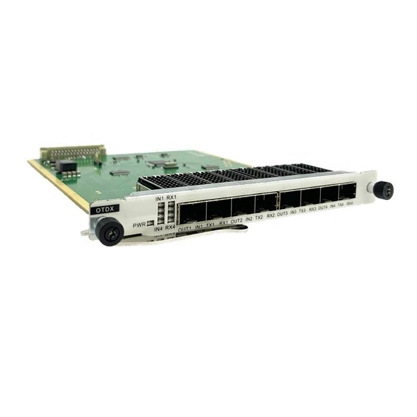
Choose an SFP module based on the fiber optic cabling that will be connected to the network switches. Traditionally, network switches have been connected using copper cables, but with the increasing demand for high-speed and reliable connectivity, fiber optic cables have gained prominence. Connecting a switch to a fiber optic network involves several steps and requires specific equipment to ensure a successful and efficient connection.
The transceiver modules are typically inserted into slots on the network switch, enabling the switch to connect to other network devices over various types of media, such as copper cables or fiber optics. Switch transceivers come in various types, each suited for. Console connection—This is a direct local management connection that you use to initially configure the switch. It plays an essential role in ensuring that data is transmitted efficiently and accurately across a network. In this video, you'll learn about Ethernet transceivers and the differences between SFP, SFP+, QSFP, and QSFP+. ” And these are usually combined within the same.
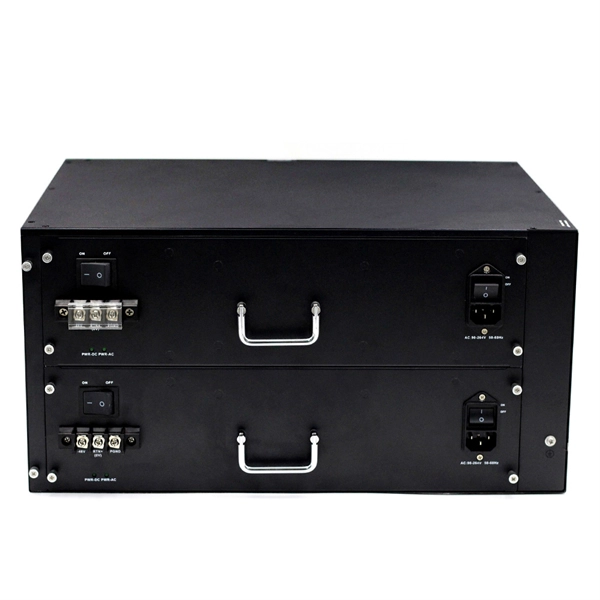
The metal box of the distribution box, the electrical installation board, and the metal base and casing of the electrical appliances in the box must be grounded. The protective neutral wire should be reliably connected through the terminal board. Are you expecting any of those 6 switches will require a neutral connection? @RobertChapin Does not. But it does require panelboard with a neutral that has more than 10 percent of its overcurrent devices rated 30 amperes or less to be protected against overcurrent by a device that has a rating not greater than that of the panelboard. It includes isolator, RCCB (Residual current circuit breaker) or RCD (Residual-current device) devices, protective fuses or MCB's (Miniature Circuit Breaker).
Multiple diodes can be driven by the same power supply as long as they are connected in series, but they must never be connected in parallel. The array is powered by a 12 volt, 1 amp wall wart. All light up but I notice that when the unit is turned on many diodes are very bright and some are not so bright. So yet again I need some help I am not really sure about building with lasers but I want to try and power multiple diodes using a single driver via parallel connections. Make sure that the optoisolator output transistor can handle the required laser diode current, and that the optoisolator input LED. Continue reading to learn five tips for troubleshooting laser diode hardware. Put together a 40 diode 5 volts serial/parallel array.
It is currently used in modern three-CCD cameras. An optically similar system is used in reverse as a beam-combiner in three- LCD projectors, in which light from three separate monochrome LCD displays is combined into a single full-color image for projection.OverviewA beam splitter or beamsplitter is an that splits a beam of into a transmitted and a reflected beam. It is a crucial part of many optical experimental and measurement systems, such as In its most common form, a cube, a beam splitter is made from two triangular glass which are glued together at their base using polyester,, or urethane-based adhesives. (Before these synthetic,. Beam splitters are sometimes used to recombine beams of light, as in a. In this case there are two incoming beams, and potentially two outgoing beams. But the amplitudes.
Contact us for competitive quotes on any of our power communication and smart grid products
Get a Quote