
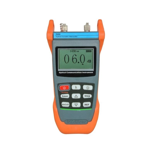
The tutorial in this section gives instructions on how to set up for a bi-directional SmartLoop test, set up the launch compensation function, make connections, do a test, and save the results. Splices are critical points in the optical fibre network, as they strongly affect not only the quality of the links, but also their lifetime. Not only does this cut the testing time by at least half, it also enables bi-directional. As the name implies, bidirectional OTDR testing is a method of optical fiber characterization and loss testing that is performed from both ends of the fiber run. The complexity of post-processing. Corning recommends that all fiber optic systems be tested to a minimum set. Optical Time Domain Reflectometers (OTDRs) play a crucial role in identifying and resolving these issues swiftly and accurately.
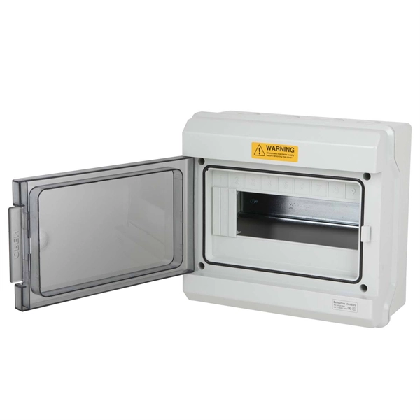
26 mm 2 (10 AWG) ground wire must be used, and in all other markets a 6 mm 2 must be used. Each DISTRIBUTION BOX and controller must be grounded. Grounding of the units: Attach a ground wire from one of. Whether you're a seasoned pro or just starting out, this comprehensive guide will give you practical insights into proper grounding techniques, with a special focus on how selecting quality materials from a reliable building material supplier impacts your entire system's safety and longevity. Here are the steps on how to ground a power distribution box: 1. Make sure all tools are intact to prevent accidents during the grounding. During the manufacturing process, metal enclosures typically have fixed points welded to the base plate or side walls. Compared to ordinary drilled bolts, these factory-preset studs offer better. The system grounding arrangement is determined by the grounding of the power source. This helps to reduce the potential difference that exists between conductive parts and the earth.
[PDF Version]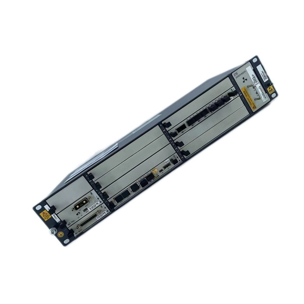
In case that the cables are placed in shafts, two different methods are recommended: Placement of cables from machine room The placement of the cables from the machine room has to be execute.
Learn how to build a waterproof fibreglass box using chopped strand matting and polyester resin and Gelcoat. This method can be used to construct composite storage tanks, pools and anything they requires a solid water tight construction. When. How to Build a Fibreglass Sub Box : This is the very first time i have tried a project like this - i had never used Fibreglass before so this entire process was a massive learning curve. I made a few mistakes which contributed to the overall time spent on finishing the project but the. Fiberglass is a widely used material in various industries due to its exceptional properties, such as lightness, corrosion resistance, and high mechanical strength. In this comprehensive guide, we will detail the process of manufacturing fiberglass parts, covering everything from material selection. Fiberglass, also called glass fiber, is made from extremely fine strands of glass. These strands are woven together or arranged randomly to form mats, fabrics, or other shapes.
[PDF Version]
The shield is connected using a clamp or an EMC-safe cable gland (PG-gland) or other method that can ensure an efficient high frequency connection. The shield connection should cover as wide an area and have as low a resistance as possible. Never connect the shield to ground. Fig. 4: Optimal grounding with star-shaped structure The quality of a shield connection is reflected in. Protective Earthing is a requirement to divert unwanted, potentially hazardous currents from all exposed metallic parts such as equipment chassis, racks, cabi-nets, cable trays, conduit, and patch panels for personnel safety reasons and to avoid potential damage to equipment. However, the idea is always the same - electrical devices are not allowed to interfere with each other. The purpose of this presentation is to introduce some practical methods. This publication gives you general guidelines for installing an Allen-Bradley industrial automation system that may include programmable controllers, industrial computers, operator-interface terminals, display devices, and communication networks.
[PDF Version]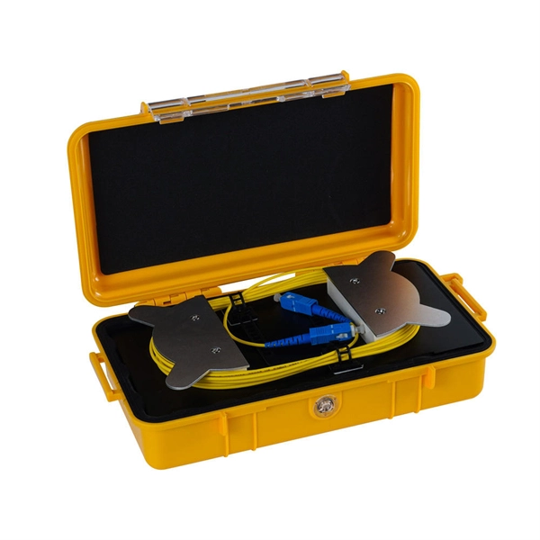
The loss value of a pigtail connector and its associated splice with matching mode field diameters should not exceed 0. Pigtail traces for all. at system. Corning recommends that all fiber optic systems be tested to a minimum set of standards. So, you drop everything and i vestigate. FOA standards align with IEC and TIA, giving you clear steps to earn trusted certification. No part of this book may be reproduced or utilized in any form or means, electronic or mechanical, including photocopying, recording, or by any information storage and retrieval system, without pe n optical fiber to a distant receiver. The electrical signal is. To be able to judge whether a fiber optic cable plant is good, one does a insertion loss test with a light source and power meter and compares that to an estimate of what is a reasonable loss for that cable plant.
Contact us for competitive quotes on any of our power communication and smart grid products
Get a Quote