
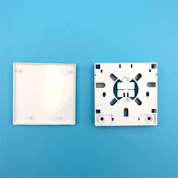
The 8 core FIB-WMP-008 optical fiber box is in accordance with the industry standard requirements of YD/T2150-2010. It's mainly used in FTTX access system terminal link. The box is made of high strength PC plastic alloy injection molding, which has good sealing and aging resistance. In addition, it. This compact 8 port ftth distribution box is designed to connect feeder cables to subscriber drop cables for FTTH last-mile fiber connectivity. It integrates fiber splicing, optical signal splitting, termination, and cable management into a fiber enclosure for indoor and outdoor applications. You can connect it with the drop cable.
Full-spectrum single-mode fibre in accordance with ITU-T G. D with optimised transmission characteristics. Suitable for the operating wavelengths in all FTTx networks. The IEC and ITU-T and under zero-dispersion wavelength and the resulting displacement of the cut-off wavelength single-mode fiber is divided into six types. 655, as required by telecom systems manufcturers and their customers. 652 (Tables A, B, C & D), IEC Specification 60793-2-50 Type B1. 3, TIA/EIA 492-CAAB and Telcordia Generic Requirements GR-20-CORE. A map illustrating the connection of IEC designations to ITU-T designations is shown in Annex I.
Picking up the best router for fiber internet isn't just about going to the market and choosing one of the best wireless routers. Instead, you need to carefully look at its specs, performance, and the type of securit.
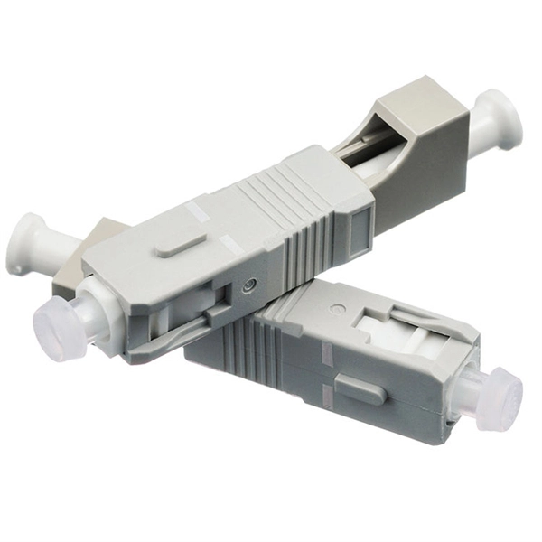
In fusion splicing, the ends of the fibers are welded together with heat. With mechanical splicing, the fibers are positioned in a self-contained unit where adhesive or a mechanical device holds. When installing a fiber optic network, connectors are required to connect both ends of the fiber optic cable. Common splicing methods include optical fiber cold splicing and optical cable hot fusion splicing. Both techniques have their advantages and are suited for different applications, but understanding which method to use can greatly impact the network's. This is where fiber optic cable splicing—the process of creating a permanent, high-performance join between two fiber ends—becomes critical. For network managers and technicians, a poor splice can lead to significant signal degradation, network downtime, and costly troubleshooting. - Process: The fibres are precisely aligned using a fusion splicing machine, and a controlled arc or laser heat source is applied to melt the fibres. The cold cure method, also known as mechanical splicing, involves the combination of anaerobic adhesive and activator.
[PDF Version]
High-quality LC-LC OM3 multi-mode breakout installation cable for indoor (inside buildings). Black protection jacket with flexible and extremely tear-resistant pulling aid of nylon material on both ends. Adopted to indoor distribution. As pigtail of communication equipment. High strength kevlar yarn member. The L-com FOB-MFD-8FM3R-M is constructed with a thick and durable 5. 6mm jacket which offers excellent strength and protection during installation and. Haile 8-core 10 Gigabit Multimode Indoor Fiber Optic Cable OM3-300 HT-200-8MT is engineered for ultra-high-speed data transmission within indoor network environments. 53 Reviews 17 Questions Fiber Count: 4 Fibers 6 Fibers 8 Fibers 12 Fibers 24 Fibers.
The core architecture of a Polarization-Maintaining Fused Coupler comprises strategically aligned optical fibers with distinct stress-inducing elements. These elements, typically composed of borosilicate or similar materials, create controlled birefringence within the fiber. What are some common uses of fiber couplers in fiber optics, including fiber lasers? What are dichroic couplers and how are they used in fiber amplifiers? What is the principle of evanescent wave coupling? What factors influence the coupling strength and wavelength sensitivity in fiber couplers?Polarization-Maintaining Fused Couplers represent a significant advancement in fiber optic technology, serving as essential components in precision optical systems. A stable measurement setup is fundamental for any successful measurement. A major cause of frustration and error is the need to continuously readjust optomechanical equipment because of continuous instabilities. an effective numerical aperture allow a better understanding which other fiber optic components are suitable for the application at hand.
[PDF Version]
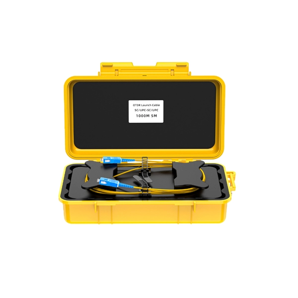
Splice the Pigtail:Fusion-splice incoming fiber to pigtail inside the box. Test:Verify light levels: -27 dBm to -8 dBm (GPON ideal). This guide provides a comprehensive overview of how to choose the right equipment, correctly install fiber and network cables, and optimize network settings to ensure reliable and efficient connectivity. 1G/10G SFP+: Standard for Gigabit and 10 Gigabit Ethernet. Fiber Optic Terminal. Step 1: Access outdoor fiber optic cables into fiber terminal box for the purpose of splicing the optical fiber cable and fiber optic pigtail, leading out it by using fiber optic patch cable. Good quality fiber laying and termination systems help achieve minimal back reflection and low signal loss.
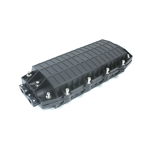
Fiber distribution box, also known as fiber optic distribution frame, is an essential component in fiber optic communication networks. It acts as a central point for terminating, splicing, and distributing these cables. In FTTH, FTTB, and other fiber access networks, terms such as Fiber Optic Termination Box, Fiber Distribution Box (FDB), and ODF (Optical Distribution Frame) are frequently mentioned.
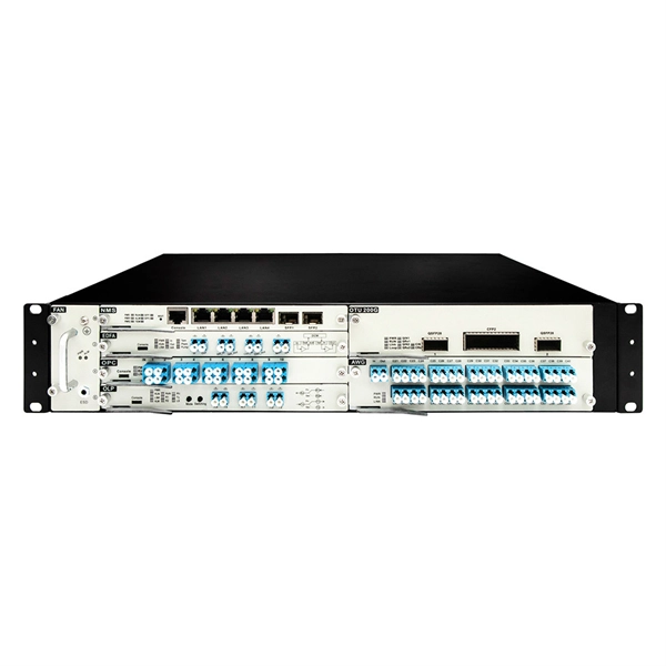
DFB and EML laser chips, along with PIN and APD detector chips, are commonly used in fiber optic communication systems to ensure reliable and efficient signal transmission. They are responsible for generating laser light, which is then modulated to carry information. There are different types of laser chips, including: VCSELs Vertical-Cavity Surface-Emitting Lasers (Vertical-Cavity. For the design and manufacturing of fiber optic transceivers, the choice of packaging methods and optical chip types is one of the key factors. But what. A photonic integrated circuit (PIC) or integrated optical circuit is a microchip containing two or more photonic components that form a functioning circuit. This article will explore the.
Contact us for competitive quotes on any of our power communication and smart grid products
Get a Quote