
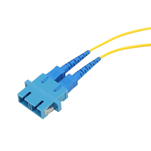
This FOA Technical Bulletin describes recommended procedures for installing and testing cabling networks that use fiber optic cables and related components to carry signals for communications, security, control and similar purposes. It defines a procedures that should provide a high level of. d suppliers of electrical construction services. Proper fiber optic. Controlling Bend Radius and Pulling Tension to Prevent Fiber Damage Confirm the mechanical limits of the selected cable type—whether armored fiber cable, industrial fiber optic cable, or standard loose-tube cables. The cable should be bent as little as possible.
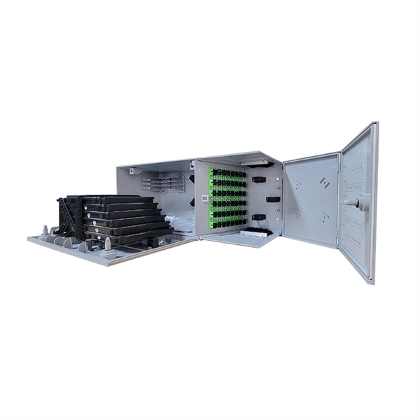
The proper installation of a distribution box involves placing it at the right height to ensure safety and convenience. This height also safeguards the box from potential. ALL DIMENSIONS ARE CONSIDERED FROM FINISHED FLOOR AND, UNLESS NOTED OTHERWISE, SHALL NOT VARY. ALL DIMENSIONS SHALL BE COORDINATED WITH ARCHITECTURAL DETAILS AND MAY BE ADJUSTED TO CONFORM WITH ARCHITECTURAL REQUIREMENTS AS LONG AS NO CODE. Dedicated Space: Dedicated electrical space is required for panel from the floor to a height of 1. Check for proper IP/NEMA ratings and material quality. Ensure safe placement: install in dry, accessible areas with good ventilation and at appropriate height (typically ~1. 5m away from the ground, and the. Standard sizes vary by type, but single-gang boxes are typically around 2″ × 3″ × 3.
This article details the comprehensive standards for installing and inspecting busbars, including support brackets, insulators, and bus duct systems. You'll learn essential guidelines and quality checks to ensure safety, reliability, and compliance in your electrical. A conductor or group of conductor used to collect the power from incoming feeders and distribute to the outgoing feeders is known as busbar. it collects the power at single point. In HV and EHV. HVT is one of the largest installation contractors of high voltage cabling & stringing, tubular busbars projects and substation equipment, as required for substation build and renewal programmes. Services include design, supply, construction and. To connect various high voltage (HV) components to the HV system, TE also delivers a wide variety of busbars. Busbars provide a safe HV connection on shorter distances. Refer to Access to the Busbar Compartments, User Guide (BQT6904800). Scope The scope of this. Alcomet are the Exclusive Reseller for TE Connectivity (TE) SIMABUS and SIMAFLEX High Voltage Power Connectors in the UK. We are also able to offer Copper and Aluminium Tubular Busbars.
[PDF Version]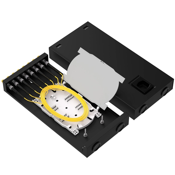
This paper explores various installation methods for FBG sensors, including embedding them within unreinforced tunnel linings in hydropower applications and attaching them directly to the inner and outer surfaces of steel linings. The authors developed techniques to attach optical fiber Bragg gratings (FBG) in the reinforcement as a means to monitor the strains experienced by the shield tunnel lining. Readings were recorded from pre-cast concrete section production through field installation and continued after field. In the process of tunnel construction, problems such as high-stress rockburst, large deformation of soft rock, water inrush and mud gushing, secondary cracking of linings, blasting interference, man-made damage, and mechanical damage are often encountered. In addition to its outstanding long-term stability, the technology offers another major advantage: it enables measured values to be transmitted over long distances, with virtually no loss in measurement quality. Their high sensitivity, durability, immunity to electromagnetic interference, and ability to perform. Home Learning Legacy Themes Engineering Civil Engineering Installation of Optical Fibre base.
[PDF Version]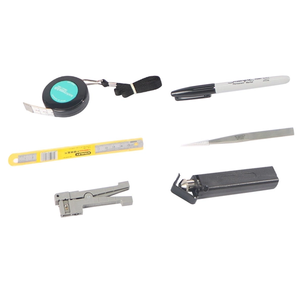
A distribution board inspection is the best way to ensure your electrical system is operating safely and reliably. Ensure safe placement: install in dry, accessible areas with good ventilation and at appropriate height (typically ~1. This prevents malfunctions, fire hazards, and unexpected power outages in your. To ensure that the electrical testing & pre-commissioning of the control, distribution, and miscellaneous panel are carried out in a manner that is risk-free, productive, and in accordance with good working practice, as required by the project work specifications. Look for any signs of burnt or damaged wiring. Additionally site team will need detailed information of all aspects associated with the installation process in order to complete the job inline with the.
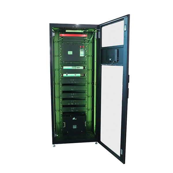
This guide provides step-by-step instructions for installing two common types of industrial switches: rack-mount, and DIN-rail switches. Choose the Installation Location: Select an appropriate spot on the DIN rail for mounting. Switches are fixed to walls or cabinet interiors using screws or hooks. Flexible placement: Choose mounting height and position based on site needs. DIN rail mounted industrial switches enable efficient. The Cisco® Industrial Ethernet (IE) 1000 Series Switches are compact rugged switches aimed to operational technology (OT) users with limited IT network knowledge. No prior experience needed—just follow along and you'll have your switch installed and running in minutes.
The bottom of an outlet box should be about 12 inches, or one foot (0. This may change depending on the type of switch or outlet. Understanding why people place light switches and outlet boxes at certain heights can be important information for installing. Both sources stipulate that socket outlets, switches and controls should be installed at a height between 450mm and 1200mm above the finished floor level. End termination which is facilitated by using a proper armoured gland kit shall be supplied and installed by CEB. Cables that are not categorized as standard underground cables. ABB Mini Center Compact distribution board is the basis for development and growth in meeting all the demands for a successful future in residential, commercial, and infrastructure segments. 01 This specification covers the design, fabrication, painting and supply of metal cabinet, supply of components, wiring, testing at works, packing and supply on destination basis and performance testing of 11 kV, 22 kV & 33 kV self-equipped metering cubicle. Service between distribution.
[PDF Version]Contact us for competitive quotes on any of our power communication and smart grid products
Get a Quote