
The Western and Northern European cable trays market encompasses the design, manufacture, and distribution of cable management systems used to support insulated electrical and data cables across industrial, commercial, and infrastructure applications. I hereby consent to the processing of my personal data in accordance with EU Regulation no. These products are designed to carry heavier cable loads compared to the. Trayco is specialised in producing and optimising 100% Belgian cable trays, mesh trays, cable ladders, mounting and floor systems. We also play an important role as advisor and guide during the installation process. Our expertise and experience have allowed us to accumulate valuable technical knowledge, which is reflected in the quality of our products.
Explore various cable tray types and sizes for electrical installations. Learn about ladder, perforated, solid-bottom, wire mesh, and channel trays in this complete guide. Each cable tray type performs a different function and comes in various materials such as aluminum. EAE cable trays and ladders provide high-strength cable protection that protects the cables from external factors. 6m can be produced upon request. Cable tray supports and. In practice, cable tray dimensions are a system of interrelated measurements —width, depth, length, and material thickness—that directly affect cable fill compliance, heat dissipation, structural loading, and long-term expandability. Wire Mesh Cable Tray. Cable tray (or cable ladder) systems are a popular alternative to electrical conduit systems, as they have an outstanding record for dependable service, design flexibility and cost savings in commercial and industrial applications. Because of its closed design, this type of tray should e used in applications where there is minimal risk of heat generation and buildup.
[PDF Version]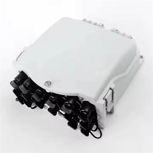
With CPO, inspecting or replacing faulty optics takes much longer. Worse, a failed optical port embedded in the package means reduced switch throughput, with no easy replacement. These concerns aren't new, but the industry has made significant strides in the last two. Co-packaged optics (CPO) technology, a key enabler for next-generation data center architectures, promises unprecedented bandwidth density and power efficiency by tightly integrating optical engines with switch silicon. But after nearly a decade of existence, where does this next-generation optical. These pressures are driving renewed momentum behind co-packaged optics (CPO). 9B by 2029, fueled largely by AI data centers. This proximity reduces power consumption dramatically. As power consumption continues to surge with the rapid expansion of AI data centers, expectations are high that CPO will dramatically. OFC 2025 made one thing clear: The transition to Co-Packaged Optics (CPO) switches in data centres is inevitable, driven primarily by the power savings they offer.
[PDF Version]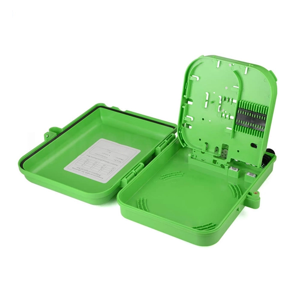
Fiber optic splicing is the process of joining two optical fibers end-to-end. Unlike using connectors, which are designed for frequent connection and disconnection at patch panels, splicing creates a permanent, stable joint with minimal light loss. The optical fiber elements are typically individually coated with plastic layers and contained in a protective tube. Fiber optic cables are the invisible highways of our digital world, carrying massive amounts of data at the speed of light. Fusion Splicing: This method involves aligning the ends of the two fiber optic cables and then fusing them together using heat. This creates a permanent and low-loss connection. Thin strands of glass bundled in cables and stretched across continents and oceans make possible much of what we take for granted today, such as the Internet, Zoom calls, electronic. The existing 2" conduit contains 4x 1/0 XLPE cable (rated for direct-burial), so I plan on pulling outdoor rated, non-metallic fiber through the same conduit. My original plan was to trench new conduit and run CAT8, but given that the existing run is all "customer side" and installed by the former.
[PDF Version]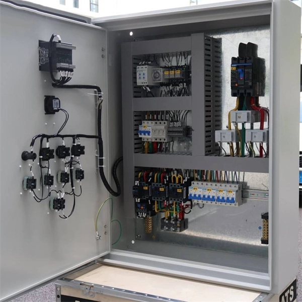
The ATTO Celerity FC-642E leverages two next-generation storage technologies – PCIe 4. 0 interconnect and Gen 7 Fibre Channel to provide an advanced storage connectivity solution with high performance, intelligence and scalability. Unleash the full potential of your storage infrastructure with high-performance Fibre Channel HBAs from ATTO. Engineered to give you the edge, Celerity HBAs. ATTO Celerity Fibre Channel HBAs deliver the fastest data throughput available for today's most demanding Storage Area Network environments. Included with all ATTO HBAs are.
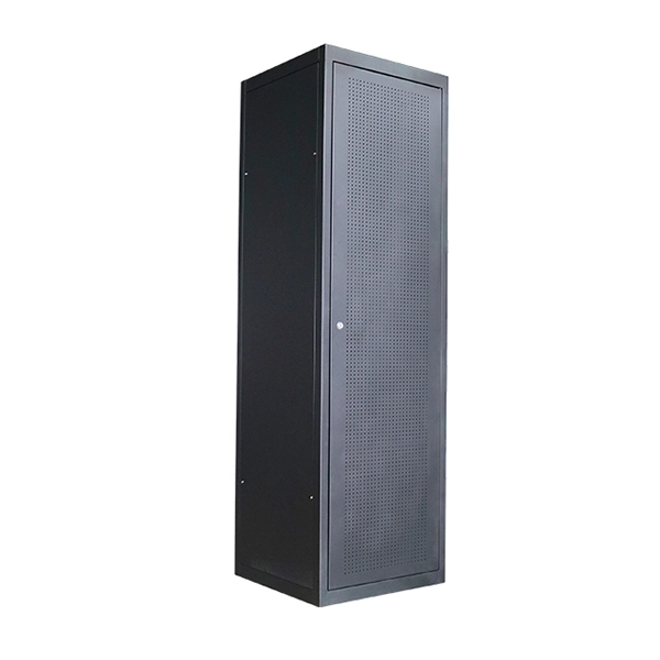
This guide covers split load vs dual RCD vs RCBO board configurations, circuit arrangement and allocation, BS 7671 labelling requirements, type testing under BS EN 61439, SPD installation, wiring best practice, and the common mistakes found during EICR inspections. An electrical panel box, also known as a breaker box or a distribution board, is a crucial component of any electrical system. It serves as a central hub for distributing electricity throughout a building, ensuring that power is delivered safely and efficiently to all the required locations. It includes isolator, RCCB (Residual current circuit breaker) or RCD (Residual-current device) devices, protective fuses or MCB's (Miniature Circuit Breaker). Extending a circuit to power multiple electrical receptacles in a residential setting requires a parallel wiring configuration, even though the physical process of running cable from one box to the next is often called a series or “daisy-chain” installation.
[PDF Version]
In a daisy-chain topology, PoE switches are connected in series, one after another. Power over Ethernet (PoE) technology simplifies infrastructure by delivering both data and electrical power through a single Category cable. As network requirements expand, understanding how to connect two PoE switches effectively becomes essential for maintaining throughput, power budgets, and. A PoE switch is a network switch that utilizes PoE technology to transmit power and data over the same Ethernet cable to powered devices such as IP cameras, wireless access points, and VoIP phones, simplifying installation and reducing maintenance costs. Can you link them together? The short answer is yes, but there are. POE switches are divided into standard POE chip machines, monolithic machines and non-standard POE switches The cascade ports of different types of switches (not POE ports) can be connected in series.
[PDF Version]
Many (MSAs) have come and gone over the years in the optical module industry. The (SFP) MSA has specified many optical module form factors over the years. • Small Form-factor Pluggable (SFP).
Contact us for competitive quotes on any of our power communication and smart grid products
Get a Quote