
Wireless communication sends information across distances without physical conductors like cables or wires. The technology makes use of electromagnetic waves that travel through free space. RoF is not a new lab experiment; it is a mature and critical "enabling technology" experiencing a surge in demand, driven by the build-out of 5G infrastructure, LEO. This white paper introduces an FPGA-based analog video transmission system over fiber optic cable, ensuring long-distance, low-latency, and interference-free video transport while maintaining compatibility with existing analog video infrastructure. System Overview The proposed solution digitizes. RF over Fiber (RFoF) was developed to address the limitations of traditional coaxial cables in transmitting high-frequency RF signals over long distances with minimal signal loss and interference. Examples of Electromagnetic energy. Transmission media refers to the physical or wireless communication channel used to carry data signals from one device to another within a computer network.
[PDF Version]
Connecting fiber optic cable takes the right tools, a steady hand, and a few simple steps: prep the fiber, make a clean join with a splice or connector, and test the link for signal quality. This article will guide you through the necessary tools, materials, and methods on how to connect fiber optic cables effectively. This guide will explain the entire set of activities involved in installing Fiber optic cable contractors -from the early planning stage right through testing-for facility managers, IT teams, and low-voltage contractors to build high-performance networks safely and efficiently. Why Use Fiber Optic Internet? Before diving into the setup, let's quickly recap why fiber optics are worth the effort: Lightning-fast speeds (up to 1 Gbps or higher). Before you start, gather the right tools. You don't want to dig around mid-job for something small but essential. Each tool helps you protect the fiber.
[PDF Version]
Acceptable splice loss in optical fiber is typically considered to be less than 0. 1. To be able to judge whether a fiber optic cable plant is good, one does a insertion loss test with a light source and power meter and compares that to an estimate of what is a reasonable loss for that cable plant. The estimate, called a "loss budget" is calculated using typical component losses for. One problem I continue to see is unexpected high loss during spicing between exchange-to-exchange network, particularly in the feeder and backbone segments, which can seriously impact the performance of the PON networks. While drop fibers from the splitter to end users often receive less attention. Are you looking for ways to improve the performance of your fiber optic splices? If so, you've come to the right place. Many factors, like core mismatch and contamination, can increase splice loss. Modern fiber optic networks usually keep splice loss. This guide reveals the secrets to fusion splicing with little fluff—just proven, straightforward techniques refined from years of work in the field.
[PDF Version]
A fiber optic coupler is a passive optical device that connects three or more fiber ends, dividing one input optical signal into two or more outputs, or combining multiple signals into one. Unlike active devices like switches or transceivers, couplers require no electrical power to. What is a Fiber Coupler? Fiber couplers belong to the basic components of many fiber-optic setups. Light from an input fiber can. This tab provides a brief explanation of how we determine several key specifications for our 1x2 couplers. 1x2 couplers are manufactured using the same process as our 2x2 fiber optic couplers, except the second input port is internally terminated using a proprietary method that minimizes back. Fiber optic coupler is one type of fiber optic component that allows for the redistribution of optical signals. In our online store, we offer you a comprehensive selection of couplers, from LC and SC to MTP, singlemode, multimode and E2000.
[PDF Version]
Light rays travel in jagged lines through a multimode fiber, causing signal dispersion. Fiber cladding consists of layers of lower-refractive index material in close contact with a core material of higher refractive index. Fiber optic networks are celebrated for their speed and reliability, but even the best systems can encounter problems. When issues like signal loss, slow speeds, or intermittent connectivity arise, systematic troubleshooting is key. This guide will walk you through diagnosing and resolving common. To determine the power budget and power margin needed for fiber-optic connections, you need to understand how signal loss, attenuation, and dispersion affect transmission. Cleaning helps your network work well.
For multimode fiber, the loss is about 3 dB per km for 850 nm sources, 1 dB per km for 1300 nm. 5 dB/km max per EIA/TIA 568) This roughly translates into a loss of 0. Optical fiber loss is a fundamental concept in fiber optic communications, representing the attenuation of light signals as they travel through fiber optic cables. Fiber. To be able to judge whether a fiber optic cable plant is good, one does a insertion loss test with a light source and power meter and compares that to an estimate of what is a reasonable loss for that cable plant. The estimate, called a "loss budget" is calculated using typical component losses for. Significant signal loss (i. Losses can be introduced by various means such as intrinsic material absorption, scattering, bending, connector loss and more. Unfortunately, it is not a simple answer and depends on several factors. Here are the details and instructions about each field and how they contribute to the calculation: 1.
[PDF Version]
Quick answer: Industry acceptance threshold for a single fusion splice is 0. 1 dB should be re-done before sealing. Acceptable dB loss for fiber depends on the component you're measuring: a single mated connector pair should lose no more than 0. 5 dB per kilometer depending on the type and wavelength. The total. To be able to judge whether a fiber optic cable plant is good, one does a insertion loss test with a light source and power meter and compares that to an estimate of what is a reasonable loss for that cable plant. The primary contributors to measured splice loss are fiber material and design factors that. Splice loss refers to the part of the optical power that is not transmitted through the splice and is radiated out of the fibre. The total loss in decibels at the fusion splice is given by the following equation, where Pin is the total power incident on the fusion splice and Ptrans is the. When using a fusion splicer, the typical splice loss is usually between 0. However, various factors, such as fibre cleanliness, core. Results from a National Electronics Manufacturing Initiative (NEMI) project, formed to improve aspects of fiber optic fusion splicing, are reported.
[PDF Version]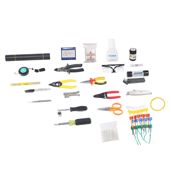
When using a fusion splicer, the typical splice loss is usually between 0. 05 dB for single-mode fibre and slightly higher for multimode fibre. 1 dB is generally considered acceptable in most fibre optic networks. Long-Term Stability: These splices are incredibly stable and reliable over time. For fusion splice loss assessment, some fusion splicers use a cross-section alignment system that images the fiber and measures geometric parameters. It is important to ensure that splice loss is kept within the specified standards to maintain optimal performance and reliability of the optical. This article explains the principle of fusion splicing, a common method for making permanent low-loss fiber splices by melting and fusing two fiber ends together, typically with an electric arc.
Contact us for competitive quotes on any of our power communication and smart grid products
Get a Quote