
Continuity testing is useful to test a few fibers in a cable before installation or to determine if a terminated cable has been damaged. Fiber optic. Regularly testing fiber optic cables helps minimize network downtime, lengthens the network's longevity, reduces maintenance requirements, and helps support network reconfiguration and upgrades. In today's fast-paced workplace maximizing productivity is essential. If it's a long outside plant cable with intermediate splices, you will probably want to verify the individual splices with an OTDR also, since that's the only way to make.
By doubling the number of electrical lanes from 8 to 16, the OSFP-XD offers 1. 6T density with 16 lanes of 100 Gb/s and 3. Support 32-ports in 1RU and 64-ports in 2U chassis. This article explains how this new 1. 6T optical module designed for next-generation data center. Optogear provides equipment and technology for manufacturing of optical fibers used in modern photonics industry. Modern specialty fibers are key components in optical lasers and amplifiers, in medical optical. HIGH-SPEED OSFP TRANSCEIVER FOR 800G/1. 3, and OIF-CMIS standards. Finnish company Orbis Oy has been providing data transmission products since 1949. Our own production enables customized solutions to be delivered quickly and flexibly. Our production plant in. TE Connectivity (TE) is expanding its high-speed connectivity portfolio with new optical transceivers, complementing our Active Optical Cables (AOCs) and copper solutions. It is a small-form-factor hot pluggable transceiver module integrated with high performance Sipho modulator.
[PDF Version]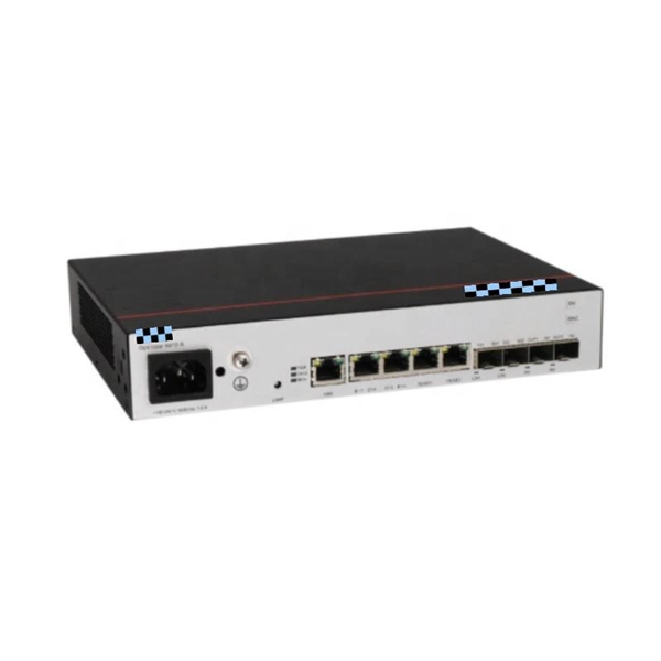
The IEC has published a new standard for the testing of fibre optic cabling. IEC 61280-4-5 provides test methods to measure the attenuation of installed multimode and single-mode optical fibre cabling plant as well as the determination of their polarity and length. Fiber optic testing of a newly installed system not only verifies that the system meets its design requirements, but also creates a performance baseline for all future testing and troubleshooting of t at system. Corning recommends that all fiber optic systems be tested to a minimum set. for installing electrical products and systems. NEIS® are intended to be referenced in contrac documents for electrical construction ation or liability to users of this publication. Lower attenuation means less signal loss over distance. Patch cords and jumper cables must meet stricter performance requirements because connectors. ANSI/TIA‑568.
[PDF Version]
In practice, a fiber network has no limitations in transmission distance, and therefore, no connection rooms, switches and panels are needed on every floor or every building. Establishing space for node rooms, equipment, cross-connection panels and switches at each level is a significant cost, often up to 70% of the total cost of the network. In the standards, this is known as centralized fiber architecture. The modem connects to a network switch which connects each remote point (rooms, floors, distributed network switches, etc. (FOA) was founded in 1995 to help develop the workforce to build the fiber optic networks to support a rapid expansion in communications and the Internet.
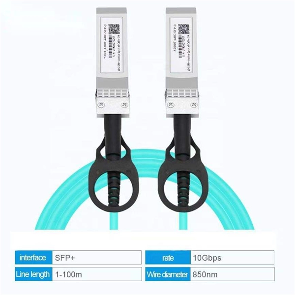
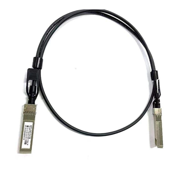
This blog introduces 4 Methods of fiber connections, including: Active Connection, Cold Splicing, Fusion splicing and Physical Connection. Active Connection Active connection utilizes various fiber optic connectors (plugs and sockets) to connect site-to-site or site-to-cable. Proper connection of fiber optic cables is essential to harness these benefits fully, as even minor errors can lead to significant. Fiber optic cable installation is a critical component in the infrastructure of modern communication systems, serving as the backbone for high-speed internet and data transmission. Over recent decades, fiber optic technology has seen significant advancements, transforming how data is both processed. The Fiber Optic Association, Inc.
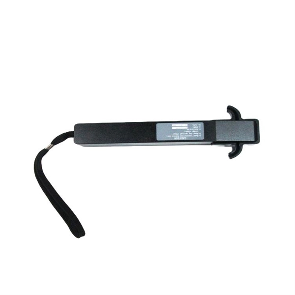
Connect a visible light source (such as a fiber optic flashlight) to one end of the cable. Take an LED flashlight and shine the light into one of the fiber. The three standard methods for testing fiber optic cabling are a visible light source, power meter and light source, and optical time domain reflectometer (OTDR). Because fiber optic transmissions work in the infrared portion. FiberLert is a fast, accurate, and safe non-contact solution for verifying fiber activity, polarity, and connectivity. First, aim your smartphone camera at the connector; most phone sensors detect the otherwise invisible 85.
Fiber Monitoring System utilizes Differential GPS (DGPS) and Cable Fault Locator technologies to accurately detect and locate fiber optic cable degradations and cuts. This identifies anomalies and weakening signals that indicate potential damage. FOGrid is FEBUS Optics' solution for cable integrity monitoring. By combining our advanced distributed fiber optic sensing technologies and our software suite with dedicated algorithms, it enables to: FOGrid: FEBUS Optics' cable monitoring solution applied to an offshore wind turbine farm FOGrid is. Cable monitoring involves the continuous surveillance and management of cable systems to ensure their optimal functioning. Continuous health is ensured through predictive maintenance and real-time.
Contact us for competitive quotes on any of our power communication and smart grid products
Get a Quote