
When using a fusion splicer, the typical splice loss is usually between 0. 05 dB for single-mode fibre and slightly higher for multimode fibre. 1 dB is generally considered acceptable in most fibre optic networks. Long-Term Stability: These splices are incredibly stable and reliable over time. For fusion splice loss assessment, some fusion splicers use a cross-section alignment system that images the fiber and measures geometric parameters. It is important to ensure that splice loss is kept within the specified standards to maintain optimal performance and reliability of the optical. This article explains the principle of fusion splicing, a common method for making permanent low-loss fiber splices by melting and fusing two fiber ends together, typically with an electric arc.
For multimode fiber, the loss is about 3 dB per km for 850 nm sources, 1 dB per km for 1300 nm. 5 dB/km max per EIA/TIA 568) This roughly translates into a loss of 0. Optical fiber loss is a fundamental concept in fiber optic communications, representing the attenuation of light signals as they travel through fiber optic cables. Fiber. To be able to judge whether a fiber optic cable plant is good, one does a insertion loss test with a light source and power meter and compares that to an estimate of what is a reasonable loss for that cable plant. The estimate, called a "loss budget" is calculated using typical component losses for. Significant signal loss (i. Losses can be introduced by various means such as intrinsic material absorption, scattering, bending, connector loss and more. Unfortunately, it is not a simple answer and depends on several factors. Here are the details and instructions about each field and how they contribute to the calculation: 1.
[PDF Version]
This article will guide you through the setup process for making an optical loss measurement on an SC/APC to SC/APC duplex link using the OptiFiber Modules OFTM-5632/OFTM-5732 along with a DTX-SFM/DTX-SFM2 adapter. Never insert an SC/APC connector into the OUTPUT PORT. While many factors influence these losses, the type of fiber optic connector used plays a crucial role. This article explores various connector types—such as SC, LC, FC, ST, APC, and UPC—and analyzes how their design and polishing affect IL and RL performance. Insertion Loss (IL): Measures the. To be able to judge whether a fiber optic cable plant is good, one does a insertion loss test with a light source and power meter and compares that to an estimate of what is a reasonable loss for that cable plant. The estimate, called a "loss budget" is calculated using typical component losses for. Use this handy tool to calculate the loss budget for your next project. Accommodating LC, SC, and MTP/MPO connectors, these panels are ideal for data centers, enterprise networks, and telecom installations.
[PDF Version]
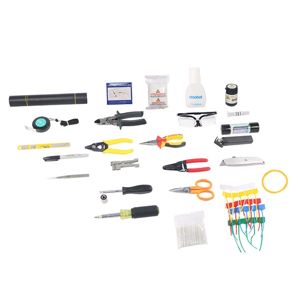
Acceptable splice loss in optical fiber is typically considered to be less than 0. 1. To be able to judge whether a fiber optic cable plant is good, one does a insertion loss test with a light source and power meter and compares that to an estimate of what is a reasonable loss for that cable plant. The estimate, called a "loss budget" is calculated using typical component losses for. One problem I continue to see is unexpected high loss during spicing between exchange-to-exchange network, particularly in the feeder and backbone segments, which can seriously impact the performance of the PON networks. While drop fibers from the splitter to end users often receive less attention. Are you looking for ways to improve the performance of your fiber optic splices? If so, you've come to the right place. Many factors, like core mismatch and contamination, can increase splice loss. Modern fiber optic networks usually keep splice loss. This guide reveals the secrets to fusion splicing with little fluff—just proven, straightforward techniques refined from years of work in the field.
[PDF Version]
In this blog post, we'll take a deep dive into the key performance tests for fiber optic patch cords — polarity verification, insertion loss and return loss measurement, 3D interferometric endface metrology, and endface inspection — along with the relevant standards . In this blog post, we'll take a deep dive into the key performance tests for fiber optic patch cords — polarity verification, insertion loss and return loss measurement, 3D interferometric endface metrology, and endface inspection — along with the relevant standards . One of the key performance indicators of a fibre optic patch cord is its insertion loss. Insertion loss refers to the reduction in power density (signal) that occurs when a signal is transmitted through the patch cord. This article explains their concepts, standards, testing methods, and FiberMania's quality assurance workflow to ensure optimal network performance. Fiber optic patch cords are crucial components in. Insertion Loss (IL) is one of the most fundamental performance indicators in fiber optic networks.
[PDF Version]Contact us for competitive quotes on any of our power communication and smart grid products
Get a Quote