
Install fiber optic connections rapidly with this field-installable fast connector designed for FTTH and outdoor applications. The arrays are manufactured using precision silicon wafer V-Groove technology or Pyrex V-Groove in conjunction with a Pyrex lid, enabling sub-micron alignment accuracy with UV cure attachment capabilities. The FITEL Ninja is a powerful, fully-automatic, state-of-the-art V-groove splicer. It is suited for metro, LAN, and fiber-to-the-home applications and can be used in a variety of applications. This high-quality. The PM V-Groove arrays are mass produced to be incorporated in various photonic devices, particularly for high speed 40 Gb/s to next generation 100 Gb/s coherent detection systems. Robust Stainless Steel - Optical fiber V groove crafted from industrial-grade stainless steel maintains. Corning offers a suite of cost-effective glass V-grooves and arrays that are pitched at 127 microns and 250 microns, with product configurations ranging from 1 to 96 channels.
[PDF Version]
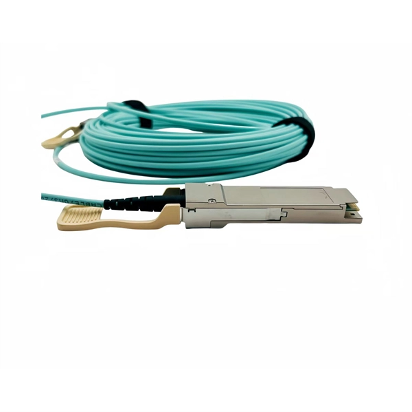
A connector housing should be used for plugging or unplugging a fiber. The unused caps can be kept in a sealed container. Also the connector requires an 8 degree polish to reduce back reflection to the equipment. Tooling needed to terminate and inspect aren't exactly. Fiber optic patch cords, also known as fiber optic patch cables or fiber jumpers, are indispensable components in modern optical networks. Unlike backbone cables, patch cords are frequently connected, disconnected, bent, and handled by technicians, making them the most vulnerable. This guide explains what fiber patch cables are, their types, connector standards, where they are used, and how to choose the right one for your data center. It is designed for flexible. This guide outlines the key steps and considerations for effective cable management in fiber optic systems.
Use launch cable to measure the first connector of the link. Increase pulse width for more dynamic range. OTDR settings are a balance between dynamic range, acquisition time, spatial resolution and accuracy. To minimize testing time, compromises must be made on accuracy (detecting low loss. OTDR (Optical Time Domain Reflectometer) testing is a vital technique for characterizing and troubleshooting optical fiber networks. It provides valuable information about fiber length, loss, and the location of events like splices and connectors. However, like any measurement technique, OTDR. An OTDR works by transmitting high-power light pulses into the fiber and measuring the light reflected from any event or the end of the fiber due to a change in the refractive index. But you may wonder, "How can I use an OTDR to locate splice loss and connector issues?" The answer is simple, with the right OTDR, you can pinpoint problem areas along the fibre.
[PDF Version]
To ensure your network functions properly, calculate total attenuation using the following formula: Practical Example (Targetting GPON Class B+ 28dB limit): Fiber Loss (5km at 0. 75dB Splitter Loss (1:32): ~17. 0dB Connectors (4 pairs at 0. 2dB Splices. In the design of broadband fiber optic access projects such as FTTH, the full attenuation of the ODN fiber optic link needs to be calculated based on the corresponding wavelength of the application system. You can apply this methodology to all types of optical fibers in order to estimate the maximum distance that optical systems use. There are no specific requirements for this document. 9807 (XGS-PON), and IEC 60794 cable standards, the ODN forms the physical optical path responsible. In modern FTTH architectures, the ODN is the physical fiber layer that distributes optical signals from the central office to end users. Operators consider ODN design as one of the most important factors affecting: Network coverage Optical loss performance Deployment cost (CAPEX) Long-term.
[PDF Version]
The combined heat shrink / crimp band combo can be used for cable jacket sizes ranging from 1. Both strain relief methods utilize the same crimp die and crimp die guide. US Conec's MMC connector is a Very Small Form Factor (VSFF) multi-fiber optical connector designed for termination of single-mode and multi-mode fiber cables up to 2. 5 mm (nominal) in outside diameter. The MMC connector employs novel TMT ferrule technology harmonized with the MT or MT-16 alignment structure. MMC Cable Assemblies and Adapters are available with 16 or 24 fibers, providing higher cabling port density and low-loss performance in a compact design to support high-bandwidth applications. ) To meet AI- and machine learning-driven demands for increased. The MMC Connector uses the new TMT Ferrule to offer high density and low insertion loss connectivity by combining a new, reduced size, MT-style ferrule (TMT) with a "very small form factor" connector body about half the size of the traditional MPO.
[PDF Version]
Buyers typically see repair costs driven by cable type, damage location, and access challenges. A failure in the optical fiber connector connection can lead to signal loss, increased optical power loss, and decreased system performance. Includes crew time for fault locating, splicing, and. Fiber Optic Center offers the service of Cross Sectioning and detailed failure analysis and also provides the equipment and training to companies that need internal capability for cross-sectioning. FOC offers this unique cross-sectioning service to identify and isolate problems related to fiber. The power budget refers to the amount of fiber optic cable plant loss that a datalink (transmitter to receiver) can tolerate in order to operate properly. Sometimes the power budget has both a minimum and maximum value, which means it needs at least a minimum value of loss so that it does not.
Handholes also known as telecom vaults or joint pits, are necessary for a fiber optic network route along its length to access the cable at periodic intervals. Sizes range from 12″ -12″. The Fiber Optic Association, Inc. I know about how a big the cable is, but is there a something else at the end of the cable to facilitate pulling it. The guide outlines best practices for cable placement in conduit, innerduct, handholes, and manhole structures and is intended for use by personnel with prior experience in planning, engineering, or placement of underground cable. (A working familiarity with underground cable requirements. When pulling long lengths of cable in conduit or innerduct (up to approximately 3 miles or 5 kilometers in the outside plant, hundreds of meters in premises cabling), use proper lubricants and make sure they are compatible with the cable jacket. Early verification of minimum bend radius and maximum pulling tension helps ensure the pathway and installation method comply with manufacturer.
[PDF Version]
There are two primary ways to clean fiber connectors: dry cleaning and wet cleaning. Each has its place — but dry cleaning is generally the safer, more consistent choice for MTP®/MPO connectors. Even microscopic dust particles can significantly attenuate light signals traveling through the fiber core. Fiber optical cassette cleaners have the typical characteristics: There are several types of fiber optical end face cleaning tools and accessories, and the goal of them is all the same - get the. clean connector is extremely important in the reliability of any optical network infrastructure. Connector end faces containing even small amounts of debris (skin oils, dust, lotions, water residue, etc. ) not only suffer from power degradation but also an increased likelihood of permanent damage. This comprehensive guide examines professional fiber optic connector cleaning methodologies essential for maintaining network performance and reliability. This is because the cleaning. The single fiber cleaners are designed to effectively clean various single fiber connectors such as LC/MU, SC/FC/ST/LSH and MDC, both residing in an adapter or fiber optic panel and unmated.
[PDF Version]Contact us for competitive quotes on any of our power communication and smart grid products
Get a Quote