
Reflectance (which has also been called "back reflection" or optical return loss) of a connection is the amount of light that is reflected back up the fiber toward the source by light reflections off the interface of the polished end surface of the mated connectors and air. It is also called. High connector loss (e., insertion loss), low return loss, or high reflectance will impair an application (i. 10GBASE-LRM) from running on a network. A high return loss is a good thing and usually results in low insertion loss. It is expressed in decibels (dB) and represents the forward power loss due to attenuation and connection inefficiencies.
In this blog post, we'll take a deep dive into the key performance tests for fiber optic patch cords — polarity verification, insertion loss and return loss measurement, 3D interferometric endface metrology, and endface inspection — along with the relevant standards . In this blog post, we'll take a deep dive into the key performance tests for fiber optic patch cords — polarity verification, insertion loss and return loss measurement, 3D interferometric endface metrology, and endface inspection — along with the relevant standards . One of the key performance indicators of a fibre optic patch cord is its insertion loss. Insertion loss refers to the reduction in power density (signal) that occurs when a signal is transmitted through the patch cord. This article explains their concepts, standards, testing methods, and FiberMania's quality assurance workflow to ensure optimal network performance. Fiber optic patch cords are crucial components in. Insertion Loss (IL) is one of the most fundamental performance indicators in fiber optic networks.
[PDF Version]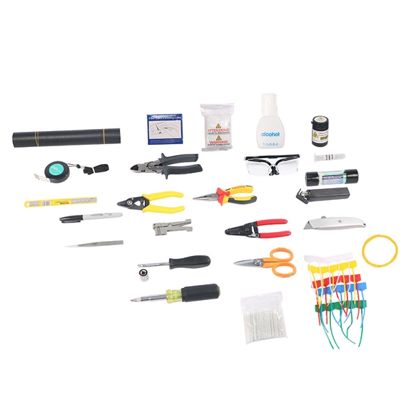
When using a fusion splicer, the typical splice loss is usually between 0. 05 dB for single-mode fibre and slightly higher for multimode fibre. 1 dB is generally considered acceptable in most fibre optic networks. Long-Term Stability: These splices are incredibly stable and reliable over time. For fusion splice loss assessment, some fusion splicers use a cross-section alignment system that images the fiber and measures geometric parameters. It is important to ensure that splice loss is kept within the specified standards to maintain optimal performance and reliability of the optical. This article explains the principle of fusion splicing, a common method for making permanent low-loss fiber splices by melting and fusing two fiber ends together, typically with an electric arc.
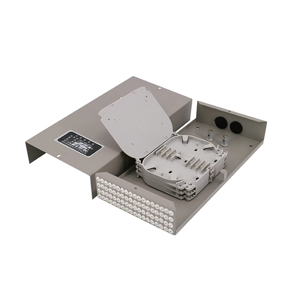
Return Loss (RL): ≥ 60 dB (APC), ≥ 50 dB (UPC). Ferrule Geometry: Must pass 3D interferometer inspection (radius, apex offset, fiber height). Among them, SC/APC Fiber Optic Patch Cords feature excellent return loss performance and high system stability, making them indispensable in optical transmission scenarios sensitive to reflected light, such as cable television networks (CATV) and passive optical networks (PON). SC (Standard. Professional Guide: This particular product is a SC to SC Fiber Patch Cord with specifications, application uses, and testing procedures. The reliability and efficiency of an optical network heavily depend on the quality of these patch. cked in one clear plastic bag. Test data sh uld be attached with each bag. Other shipping. We offer full-service OEM and ODM solutions for fiber optic cables, assemblies, and connectivity products — from design and prototyping to global production and logistics. Multimode SC-SC Duplex Patch Cab. It is dismountable, flexible and featured wit small size, low insertion loss and lower price.
[PDF Version]
Acceptable splice loss in optical fiber is typically considered to be less than 0. The calculated loss budget is an estimate that assumes the values of component losses and does not take into account the uncertainty of the measurement. This testing will ensure that the data necessary to properly evaluate any future system malfunctions will be av nctioning. So, you drop everything and i vestigate. He's right – it is n t working. What is the typical acceptable splice loss for single-mode fiber using fusion splicing? What is the acceptable splice loss for multimode fiber using mechanical splicing? How does fiber alignment affect splice loss? Why is cleaning the fiber important before splicing? What role does the cleaver play. Splice loss refers to the part of the optical power that is not transmitted through the splice and is radiated out of the fibre. The total loss in decibels at the fusion splice is given by the following equation, where Pin is the total power incident on the fusion splice and Ptrans is the.
[PDF Version]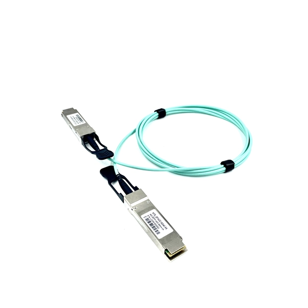
In 1966, Kao proposed that it would be possible to make a low-loss optical fiber using impurity-free silica glass (SiO2). (1) After subsequent technological develop-ments, a low loss of 17 dB/km was demonstrated by Keck et al. in. 1930s-1950s – Fiber Bundles for Imaging: Researchers started using fiber bundles to transmit images, particularly for medical endoscopes. However, these early fibers suffered from extremely high signal loss—over 1,000 dB/km, making them impractical for long-distance communication. This comprehensive review explores OFC's historical evolution, core principles, components, and versatile applications. Optical fibers, core components of global communication infrastructure, are capable of transmitting data over long. Fiber loss, also called fiber optic attenuation or attenuation loss, refers to the loss of signal between input and output.
A uni-directional test will be conducted on all pigtail splices with no greater than a. 8 dB after 5 repeated attempts results in the replacement and re-splicing of that pigtail. dB loss in fiber optics is the reduction in light signal strength as it travels through a fiber cable, measured in decibels. The connector end is polished and tested under factory conditions, ensuring low insertion loss and high return loss. 1 dB per 100 feet (30 m) for 850 nm, 0. For singlemode fiber, the loss is about 0. While some loss is expected, excessive or unexpected loss can lead to poor performance, network downtime, and signal failure. Recognizing what constitutes too much loss is essential. At TREND Networks, we are frequently asked how much loss is allowed when conducting testing on fibre optic cabling.
Contact us for competitive quotes on any of our power communication and smart grid products
Get a Quote