
Silicon photonics has developed into a mainstream technology driven by advances in optical communications. The current generation has led to a proliferation of integrated photonic devices from t.
In, an eye pattern, also known as an eye diagram, is an display in which a from a receiver is repetitively sampled and applied to the vertical input (y-axis), while the data rate is used to trigger the horizontal sweep (x-axis). It is so called because, for several types of coding, the pattern looks like a series of eyes between a pair of rails. It is a tool for the evaluation of the combi.
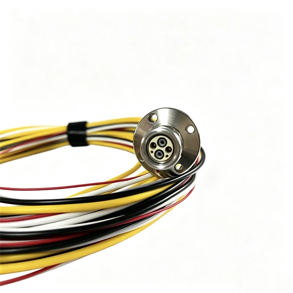
ODM electrical wiring devices represent a comprehensive solution for modern electrical installations, offering customized manufacturing services that cater to specific industry requirements. Manufactured with precision under OEM/ODM customization, this cable assembly supports various configurations to meet specific project requirements. FUTINA design and production standards can meet most of the world's. In this guide, we break down the OEM vs ODM debate by defining both, comparing their benefits, and explaining how companies like Kenvox support businesses across both contract manufacturing models. ## Real Project Snapshot — Oem Vs Odm Wire Harness *Anonymized example from our case bank, shared so buyers can see how this scope is actually executed in production. We offer complete hardware and software solutions, from development and PCB layout to prototyping, connectivity.
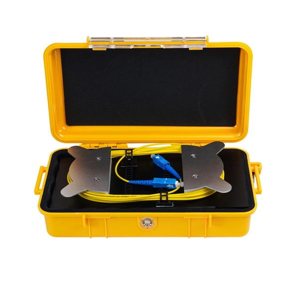
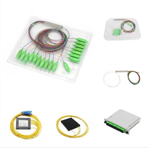
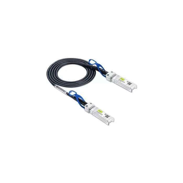
Home and business fiber optics projects typically range from a few hundred to several thousand dollars, depending on run length, fiber type, and labor needs. The main cost drivers are materials, installation time, and environmental factors that affect trenching, conduit, and. Fiber Optic Wall Mount Box with LC Couplers for Single Mode & Multimode Fiber Optic Cable. | Fiber Box Enclosure for MPOE's, Network Rooms, and IDF Rooms. (LC 6 Strand OS1/OS2) Need help?Discover fiber optic junction box prices with IP65 waterproof ratings, ABS/PC materials, and FTTH applications. Additionally, we have Outdoor Harsh. Fiber Optic Connectors are electrical connectors that terminate the end of an optical fiber, and enables quicker connection and disconnection than splicing.
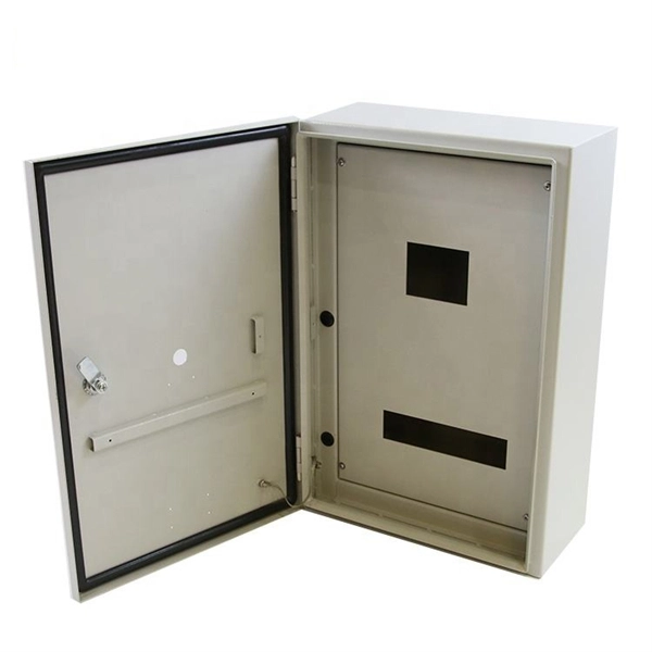
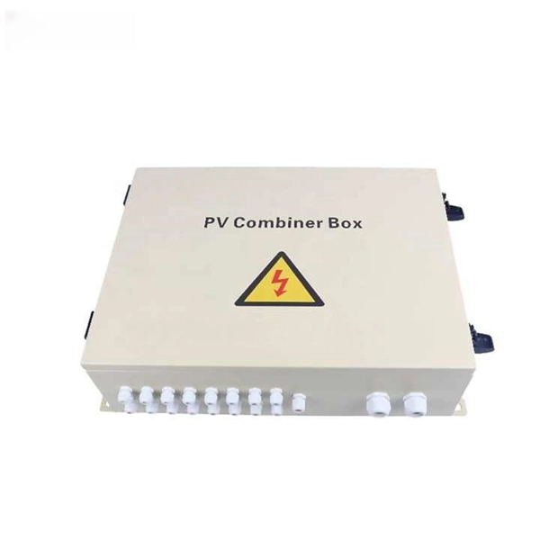
Ensure safe placement: install in dry, accessible areas with good ventilation and at appropriate height (typically ~1. Distribution Board or DB is an electricity supply system or a common enclosure that distributes the electrical power feed into subcircuits. It includes isolator, RCCB (Residual current circuit breaker) or RCD (Residual-current device) devices, protective fuses or MCB's (Miniature Circuit Breaker). Leaders in lighting connection and control products, flex7 design and manufacture all of our innovative products in the UK. Whether it's a home, office, or factory. Hey, in this article we are going to see the Single Phase Distribution Box Wiring Diagram and Connection Procedure. The box contains protective devices that can be used to protect individual circuits in order to switch them off quickly and safely in the event of a.
Pick good-quality wires to make the system work better and safer. Keep cables organized to stop overheating and make repairs easier. Choosing the right electrical wires for a telecom cabinet is crucial for ensuring optimal performance and safety. The Importance of Standardized Cabinet Wiring. Network Cabinet systems systematically address challenges in computer applications such as high-density heat. Low-voltage wiring is everywhere. The rapid and continuous expansion of technology from simple wiring for telegraphs and telephones to complex structured cabling networks for data, voice, audio/visual, Wi-Fi, and many other systems has created an electrical industry specialty. It is commonly used in residential buildings, offices, and other commercial spaces to facilitate communication between individuals. Each module is connected to its own run of cable (two modules in one place; two cables.
[PDF Version]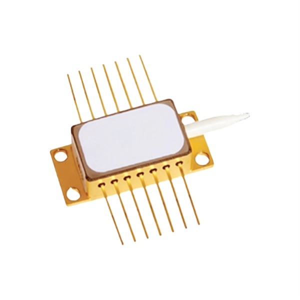
Standard high voltage connectors for voltages up to 100kV. When required, cables can be supplied terminated with HV connectors. Our PCON products include a range of high-voltage (HV) terminals specifically designed to support the increased connectivity requirements of HV interconnection systems in hybrid and all-electric vehicles. 50mm pitch with a nominal current carrying capacity of 3A.
What Is a Distribution Box?A distribution box, also known as a power distribution unit, is a critical component in any electrical system. It is the control center fo.
To solder the wires to the relay, tin the end of the required wire, and bend the tinned end of wire in the middle with needle nose pliers to form a "U" shape. Please refer to them during installation in order to avoid problems. The protective measures used will determine suitability for automatic soldering or automatic cleaning. Please follow the recommendations. As electronic devices become more compact, it is becoming a common practice to weld the relay to a PC board (along with the semiconductors) rather than using plug-in relays with sockets. When relays are welded, their functionality may be affected due to seepage of flux into the relay. Where to find. In this guide, I'll walk you through pro-level soldering techniques, safety tips, and insights from real PCB assembly challenges.
Contact us for competitive quotes on any of our power communication and smart grid products
Get a Quote