
For instance, a 1:8 splitter ratio signifies an equal distribution of incoming optical power among eight output ports, with each port receiving 1/8th of the total power. Common splitters include 1x2 fiber. Cost Efficiency: A single OLT port can serve 8–64 ONTs via a splitter, reducing the number of OLTs, fibers, and deployment labor needed. Passive Operation: Splitters have no active electronics, so they require no power, cooling, or maintenance—lowering operational costs (OPEX) for ISPs. While 1:n or 2:n couplers are most common, there are n:n couplers also, e. These devices are generally bidirectional. With a 1:n device, in one. In fiber optic networks, particularly in FTTx (Fiber to the x) and PON (Passive Optical Networks) deployments, splitters play a central role in distributing the optical signal from a single source to multiple destinations. In this article, we'll explain the concept of split.
[PDF Version]
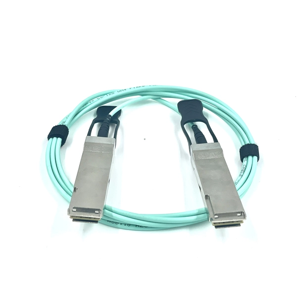
The Fibre Channel physical layer is based on serial connections that use fiber optics to copper between corresponding pluggable modules. The modules may have a single lane, dual lanes or quad lanes that correspond to the SFP, SFP-DD and QSFP form factors. Fibre Channel does not use 8- or 16-lane modules (like CFP8, QSFP-DD, or COBO used in 400GbE) and there are no plans to us. OverviewFibre Channel (FC) is a high-speed data transfer protocol providing in-order, lossless delivery of raw block data. Fibre Channel is primarily used to connect to in (SAN) in co. When the technology was originally devised, it ran over optical fiber cables only and, as such, was called "Fiber Channel". Later, the ability to run over copper cabling was added to the specification. In order to avoid confu. Fibre Channel is standardized in the of the International Committee for Information Technology Standards (), an (ANSI)-accredited standards c.
[PDF Version]
The formula is simple: sum the cross-sectional areas of all cables inside the conduit, divide by the conduit's inner area, multiply by 100. Use this calculator to estimate total optical attenuation across your network and confirm system performance against recommended design margins. The tool accounts for fiber attenuation, connector and splice losses, splitters, and other passive components, helping ensure reliable transmission in. A tool that computes how many fibers fit in a circular bundle and splits them into user-defined segments for cable-assembly planning. Key Parameters: • Center Diameter, Fiber Diameter, Packing Efficiency, Section Count Calculation: Visualization: • Color-coded radial diagram with per-section. Fill ratio — sometimes called fill percentage — is the ratio of the total cross-sectional area occupied by cables to the interior cross-sectional area of the conduit, expressed as a percentage.
[PDF Version]
Distribution transformers are normally located at a, where wires run from a utility pole or underground power lines to a customer's premises. They are often used for the power supply of facilities outside settlements, such as isolated houses, farmyards, or at below 30 kV. Another application is the power supply of the overhead wire of electrified with AC. In this case, single-phase.
Indoor Fiber Optic Cables: These are typically lighter as they require less protection. The cable is suitable for both indoor and ou door installation. The outer sheath is made from black UV-stabilized and weather resistant material which is SHF1 classified, and may be exposed for shorter periods to fluids such as diese and mineral oils. The resistance to these. This calculator will allow you to find the fill ratio using one, two, or three cables within the conduit. Description of materials used in fiber optic cables 2. Explanation. Of course the cable is much lighter than copper but much heaver than you are used to with fiber - it weighs 752 kg/km or about 1/2 pound per foot.
This guide covers the cable tray types and their appropriate applications, the fill rules for each configuration, ampacity derating requirements, separation of power and signal cables, and the decision criteria for choosing cable tray over conduit. Properly sizing your cable tray is critical for safety and compliance. Cable tray is the preferred wiring method for industrial facilities, data centers, and large commercial buildings where routing dozens or. Calculate cable tray fill ratio, weight loading, and derating factors for multi-standard compliance. This calculator features an interactive interface with advanced visualizations. Below — how to land on the right size the first time. A tray that's too narrow forces you to add a parallel run or re-draw the supports.
Contact us for competitive quotes on any of our power communication and smart grid products
Get a Quote