
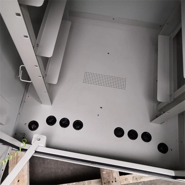
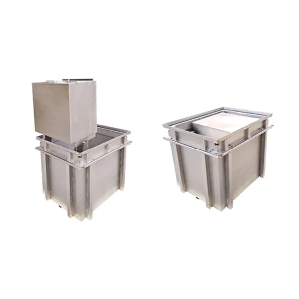
The bottom of the board (box) installed on the ground should be 5-10 mm higher than the ground; the center height of the operating handle is generally 1. 2 m in front of the box; the protective wires are reliable; bare. Determine the total electrical power usage of the warehouse and, calculate the electricity demand for each area, workshop, machinery, equipment, etc. Choose electrical equipment with appropriate power ratings to meet usage requirements, ensuring sufficient load for the electrical system. However, the key to a safe and reliable system lies in proper installation. Done right, it ensures. In industrial power distribution systems, cable distribution boxes (also known as power distributor boxes, distribution electrical boxes, or electrical power distribution boxes) are the core hub of power transmission, branching, and protection. Electricity flows through. Distribution boxes shall be made of non-combustible materials; open distribution boards may be installed in production places and offices with low electric shock risk; enclosed cabinets shall be installed in processing workshops, foundries, forging, heat treatment, boiler rooms, woodworking houses.
[PDF Version]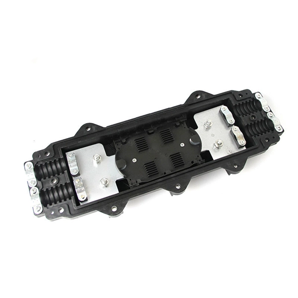
The primary rulebook used in the safe use of cable trays is NEC Article 392. This is a description of how to select, install, and support these metal or plastic frames, on which electrical wires are installed. The purpose is to provide guidance for preparing accurate and complete electrical designs that are cost effective, energy. The Unified Facilities Criteria (UFC) system is prescribed by MIL-STD 3007 and provides planning, design, construction, sustainment, restoration, and modernization criteria, and applies to the Military Departments, the Defense Agencies, and the DoD Field Activities in accordance with USD (AT&L). This Specification is one ofa series prepared by Defence Estates (DE) an agency ofthe Ministryof Defence (MOD) primarilyfor usein its contracts for mechanical and electrical engineering works. The Specificationcovers electrical installations for buildingsother thandwellings. It is a revision ofthe. en completely installed, without damage either to conductors or structural system use maintain spacing or to keep cables in place when the tray is ect the minimum bend ra-dius for cables as they exit the bottom of the cable tray.
[PDF Version]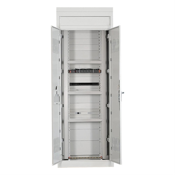
Successfully installing a new head unit requires a precise understanding of automotive electrical connections and proper preparation. Upgrading a vehicle's audio system often begins with replacing the factory head unit, also known as the car stereo receiver. The most important connections are power, ground, and speaker wires, which must be correctly identified and attached for optimal performance. Start. ⚠️ Reversing these wires can drain your battery or damage electronics! • Always has power (even when car is off) • Maintains radio memory and clock • Connect to yellow wire on head unit ⚠️ WARNING: Never reverse these connections! Connecting yellow to red or red to yellow will drain your battery or. If you're planning to upgrade your car sound system, one of the most important parts of the process is making sure your new head unit matches your overall setup. Whether you're a total beginner or a seasoned DIY installer, following the right car audio installation steps can prevent wiring issues. When it comes to installing a new head unit in your car, one of the first things you'll need is a wiring diagram.
[PDF Version]
Discover locator tools that protect electrical wires during drywall cutouts. Choose from magnetic targets or pointed markers for precise box location. Locate with a Guide Point Bit or Strong Magnet. Each option uses a pointed tip, durable materials, and. The Blind Mark will help you get perfect drywall cutouts with no measuring. When you're ready to cut the hole, hold the Blind Mark Locator magnet over the area where you think the receptacle is located. This guide highlights top drywall outlet markers that eliminate guesswork and deliver clean, professional results.
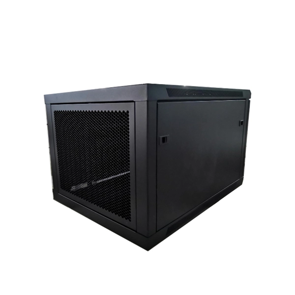
In this guide, we'll break down everything you need to know to install a distribution box correctly and confidently. Choose the right box based on environment (indoor/outdoor), load capacity, and durability. Check for proper IP/NEMA ratings and material quality. It takes the incoming power and safely distributes it to different circuits throughout your building. This article mainly talks about the first one. An electrical distribution box, also known as a power distribution box, panelboard, or consumer unit. The steps to install a small distribution box include selecting a suitable location, installing the base, placing the distribution box, connecting the wires, and checking for acceptance. Select location Before. affect Type B MCB distribution boards and their protective d bar arrangement designed to accept single and/or double pole OCPDs. It receives power from the main electrical supply and divides it into separate circuits, each. In modern electrical systems, cable distribution boxes (also known as electrical distribution boxes or distribution boxes) play a crucial role as the key hub for managing, distributing, and protecting circuits.
[PDF Version]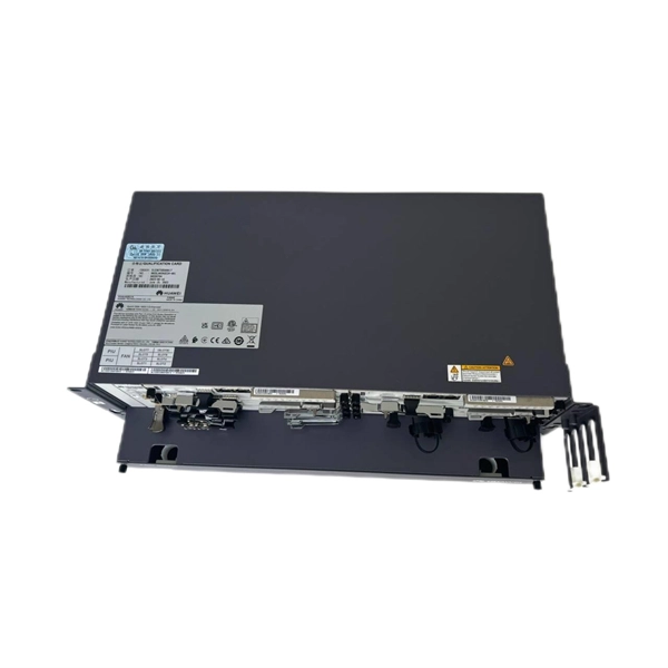
Learn how to install a distribution box safely and correctly. It takes the incoming power and safely distributes it to different. The installation of electrical systems during the construction of pre-engineered warehouses and factories plays a vital role in overall project quality, especially when integrated with shed fabrication processes to ensure safety, accuracy, and effective long-term operations. Covers wiring, placement, standards, and expert tips for a compliant setup. The electrical installation process for a. Industrial plants constitute a system composed of production facilities, transport and storage possibilities, as well as office and infrastructure facilities.
In hazardous areas, fibre-optic cables, especially directly inserted into flameproof chambers, are considered potentially more critical than copper wires. In this case, it is not relevant how much energy is trans.
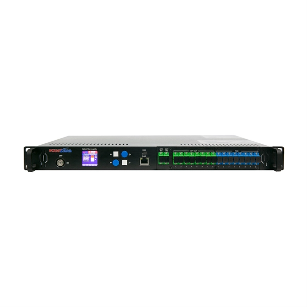
Power Connection: The ONT box requires power to operate, so it's plugged into a nearby electrical outlet. Testing and Activation: The engineer tests the connection to ensure it's working correctly and activates the ONT box. Router/Device. FTTP or fiber To The Premises applications have reinforced the importance of reliable and stable fiber optic terminations. They also feature resistance to moisture, impact, chemical exposure. There are a number of factors that need to be considered when it comes to proper installation of a fiber termination box that involves ensuring safety, accessibility, and performance in the same package. Inspect the capacity and consequently, the compatibility with adapters (SC, LC, FC, ST). Here are some basic installation steps: 1.
Check for proper IP/NEMA ratings and material quality. Ensure safe placement: install in dry, accessible areas with good ventilation and at appropriate height (typically ~1. Practice good wiring: secure grounding, neat cable management, proper insulation, and correct wire. Strictly speaking, the word “Distribution Box (D-box)” can refer to two categories: electrical distribution boxes and septic tank distribution boxes. This article mainly talks about the first one. Whether it is residential buildings, commercial facilities or industrial sites, the. In the USA and Canada (following NEC and CEC), distribution transformers typically receive 4. 2 kV on the primary side and step it down to 120V single-phase and 120/240V split-phase for residential applications. The primary side of the distribution transformer is supplied by two conductors. Material preparation: Prepare the required circuit breakers, wires, wiring ties and other materials, and ensure that they meet the design drawings and installation requirements.
[PDF Version]
Download a comprehensive set of Cable Tray Installation CAD Blocks in DWG format, ideal for electrical engineers, MEP designers, and industrial layout planners. This collection includes installation details for ladder trays, perforated trays, solid-bottom trays, and wire mesh trays, along with. Tray installation details for the location of a project's electrical wiring; in addition to blocks with different angles that allow the wiring circulation to be identified. Perfect for electrical engineers and contractors, this plan ensures an efficient and organized cable management system for commercial and industrial. Digital tools like BIM and advanced CAD software are revolutionizing the creation and sharing of cable tray installation drawings, enabling more precise planning, clash detection, virtual walkthroughs, and smoother coordination between engineering teams and installation crews. Want to explore more. Method Statement installation of Cable Trays and Ladders - Planning Engineer FZE. Tray assembly in mt steps and cuts.
[PDF Version]Contact us for competitive quotes on any of our power communication and smart grid products
Get a Quote